How Deck Sheet Length Impacts Handling and Installation
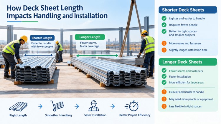
In structural steel construction, the length of a metal deck sheet is far more than a dimensional specification — it is a critical design variable that shapes jobsite logistics, labor productivity, erection safety, and long-term structural performance. While much attention is paid to deck profile, gauge, and coating, sheet length decisions are often made late in the design process without full awareness of their downstream consequences. Whether you are detailing a composite floor system, a roof deck assembly, or a long-span structural configuration, the sheet length you specify directly determines how panels are transported, staged, lifted, and fastened. Longer sheets can reduce the number of end laps and field connections, but they introduce handling challenges that shorter sheets avoid. Conversely, shorter sheets are easier to maneuver in tight bays but multiply the number of seams and fasteners required.
Sheet Length Fundamentals: What Changes When Dimensions Shift
Standard Length Ranges and Why They Matter
Metal deck sheets are commonly manufactured in lengths ranging from 6 feet to 40 feet or more, though standard stock lengths typically fall between 8 and 32 feet. Custom lengths are available from most fabricators and are frequently specified on projects where bay spacing drives the geometry. The choice between standard and custom lengths involves a tradeoff: standard lengths minimize lead times and cost, while custom lengths reduce field cutting waste and improve structural efficiency.
When sheet length increases, several variables shift simultaneously. The panel's self-weight increases, requiring higher crane capacity or more careful rigging. Deflection under its own weight before attachment becomes a handling concern, particularly for lighter gauges like 22 or 20 GA. The moment of inertia of an unattached panel over a long unsupported span can result in visible sag or bow, complicating alignment during placement. Structural engineers specifying long sheets on projects with wide bay spacing must account for this temporary condition in their construction sequence documentation.
Shorter sheets, while more manageable, increase the frequency of end-lap conditions. Each end lap represents a connection point requiring additional fasteners, side-lap stitching coordination, and careful inspection to ensure proper bearing on the supporting framing. In diaphragm-critical applications, the number and quality of end laps directly influence the calculated shear capacity of the deck assembly — a relationship well-documented in the SDI Diaphragm Design Manual and reflected in Consac's deck detailing standards.
Transportation Constraints That Drive Length Decisions
Before a single sheet reaches the jobsite, its length has already determined how it will be shipped. Standard flatbed trailers accommodate loads up to 48 feet in length, but permit requirements, route restrictions, and load-securing regulations can effectively limit practical shipping lengths to 32–36 feet in many jurisdictions. Sheets exceeding these thresholds require oversize load permits, escort vehicles, and often nighttime delivery windows — all of which add cost and scheduling risk.
Bundling configurations also depend on sheet length. Longer bundles are heavier per lift and may require spreader bars to distribute crane loads evenly, preventing deck damage from concentrated pick points. Short sheets, on the other hand, can often be hand-carried or managed with smaller equipment, offering flexibility in phased construction or renovation projects where crane access is limited.
Handling Risk Factors
Design Coordination Checkpoints
Long sheets reduce end laps and field connections, but require precise pre-planning of crane picks, rigging points, and temporary bracing to prevent panel damage before attachment.
Sheet length is not just a procurement decision. It directly affects handling, transportation, structural behavior, erection sequencing, and overall project efficiency.
Sheet length does not operate in isolation — it is intrinsically linked to the installation sequence, the configuration of end and side laps, and the resulting structural behavior of the completed diaphragm. Understanding these relationships allows engineering teams to optimize both constructability and structural performance simultaneously.
End laps must occur over supporting framing — joists, beams, or girders — and must provide adequate bearing for both sheets. The SDI and AISC require a minimum bearing of 1½ inches for each sheet at end laps, meaning the supporting member flange must be wide enough to accommodate both panel ends simultaneously. When sheet lengths are not coordinated with framing spacing, the detailer may be forced to introduce filler pieces or shift lap locations off-center, compromising both structural performance and field efficiency.
Consac's joist and deck detailing workflow addresses these coordination requirements in depth, emphasizing early layout confirmation before shop drawings are finalized.
Sidelap fasteners — typically screws, button-punches, or welds — connect adjacent panels along their longitudinal edges and are critical to diaphragm shear transfer. The required sidelap fastener spacing is determined by the calculated diaphragm demand and is independent of sheet length. However, longer sheets reduce the number of end laps, which are structurally weaker connection zones, effectively improving the diaphragm's uniformity and shear efficiency. In high-diaphragm-demand zones (lateral resisting systems, seismic design categories C and above), optimizing sheet length to minimize end laps per bay can meaningfully increase allowable diaphragm shear without changing gauge or profile.
Cambered beams present a unique challenge for long deck sheets. A beam cambered to offset anticipated dead load deflection will have a slightly curved top flange profile at time of deck installation, before loading has occurred. Long sheets spanning across cambered members may not lie flat during placement, creating gaps at intermediate supports and complicating puddle weld or powder-actuated fastener installation. Detailers should flag beam camber values on erection drawings and sequence deck installation to account for the temporary elevation differential — particularly when multiple cambered beams run parallel and the deck sheet must bridge between them. This is a coordination challenge that becomes more pronounced as sheet length increases.
Begin deck installation at the building core and work outward to maintain erection stability
Attach perimeter sheets first to establish reference alignment before interior runs
Temporarily tack long sheets at midspan before final fastening to prevent wind uplift
Sequence crane picks to avoid walking loaded bundles across freshly fastened sheets
Coordinate with ironworkers on temporary bridging removal timing relative to deck attachment
Verify sheet orientation (flute direction) matches structural drawing before placement
Long sheets reduce the frequency of field cuts at building perimeters and openings — a meaningful productivity advantage since deck cutting is labor-intensive and generates significant waste. However, when field cuts are required on long sheets, the proportion of scrap is higher per cut event. Detailers can minimize total field cutting by specifying sheet lengths that align with bay dimensions, using partial-length sheets at building edges, and clearly dimensioning all cut locations on erection drawings.
Penetrations for mechanical, electrical, and plumbing runs also interact with sheet length. A long sheet spanning across a large opening zone may require a cut that effectively reduces it to a non-standard piece, affecting its contribution to diaphragm capacity. Early coordination between the structural detailer and MEP trades — ideally during BIM coordination — prevents last-minute field modifications that weaken the deck assembly.
Learn more about how Consac approaches steel joist and deck detailing coordination in complex multi-trade environments.
Installation Sequencing, Lap Configuration & Structural Behavior
End Lap Placement & Bearing Requirements
Sidelap Stitching & Diaphragm Shear Capacity
Camber Interaction with Sheet Alignment
Installation Sequence Best Practices
Field Cutting Considerations
Sheet-length decisions influence far more than material quantities. They affect installation labor, crane utilization, fabrication efficiency, project scheduling, shop drawing coordination, and field productivity. The most successful deck layouts balance structural requirements with practical construction realities from the earliest stages of design.
Sheet length has a direct impact on installation labor requirements. Longer sheets reduce the number of crane picks, alignment operations, temporary attachments, endlaps, and fastening sequences required across a floor plate.
Replacing multiple short panels with a single longer panel can eliminate several repetitive placement cycles. However, the advantage disappears when site access, crane capacity, lifting radius, or handling constraints make oversized sheets difficult to maneuver.
The optimal solution balances panel weight, crane capability, erection efficiency, and site logistics rather than maximizing sheet length alone.
Custom-length deck sheets generally carry a fabrication premium when compared with standard stock lengths. However, the premium is frequently offset by reductions in waste, minimized field cutting, fewer endlaps, and a lower overall sheet count.
Repetitive layouts can benefit substantially from exact-length panel specifications that align with bay dimensions. This approach minimizes cutoffs and maximizes manufacturing efficiency across large projects.
Material optimization must also account for gauge requirements. Longer sheets may require heavier gauges to satisfy construction-stage loading and deflection limits, creating a tradeoff between sheet count reduction and material cost.
Estimated reduction in installation labor hours when optimized sheet lengths eliminate one endlap per repetitive bay.
Governs support flange sizing and coordination requirements throughout the layout.
Typical maximum sheet length before oversize transport restrictions become a project constraint.
Sheet-length decisions established during design must be communicated consistently through every project document. Structural framing plans, deck erection drawings, fabrication details, material schedules, and contractor installation plans must all reflect the same panel-length strategy.
Ambiguity in sheet-length requirements frequently results in RFIs, field substitutions, and schedule impacts. Best practice requires clear documentation of intended panel lengths, acceptable substitution ranges, bearing requirements, and endlap locations relative to structural supports.
Thoroughly coordinated erection drawings should identify each panel's position, length, orientation, support relationship, and fastening requirement, ensuring all project stakeholders operate from a common understanding.
Modern BIM-enabled workflows allow every deck sheet, endlap, bearing condition, and transition zone to be modeled before fabrication begins. Coordinated digital models provide early visibility into diaphragm continuity, framing alignment, cut-sheet requirements, transport constraints, and installation sequencing challenges.
Identifying conflicts during model review substantially reduces fabrication changes, minimizes field modifications, and improves schedule certainty throughout construction.
Sheet-length optimization is a multidiscipline decision involving design, fabrication, logistics, erection, and project management. The greatest value is achieved when structural engineers, detailers, fabricators, and erection contractors collaborate early to balance labor productivity, material efficiency, shipping limitations, and installation practicality. Projects that treat deck length as a coordination strategy rather than a drafting detail consistently achieve lower costs, fewer RFIs, smoother installations, and stronger schedule performance.
Practical Impacts on Labor, Cost & Project Coordination
Labor Productivity & Crew Efficiency
Material Cost Implications
Key Design & Coordination Benchmarks
Coordination with Structural Drawings & Shop Drawings
Digital Modeling & BIM Validation
Final Engineering Takeaway
Selecting the right deck sheet length is a multidisciplinary decision that integrates structural performance, logistics, labor productivity, and project coordination. The following framework distills the core principles into actionable guidance for engineers, detailers, and construction professionals at every project stage.
Sheet length is a first-order decision — not a detail. Engage the erection contractor, deck fabricator, and structural detailer in the length selection process during design development, not after construction documents are issued. The cost of late changes far exceeds the effort of early coordination.
Key Takeaways & Decision Framework for Sheet Length Specification
Summary: The Sheet Length Decision Matrix
What's Your Reaction?