Composite Deck • Pour Sequencing • Construction-Phase Loading
Why Pour Sequence Is a Structural Engineering Decision
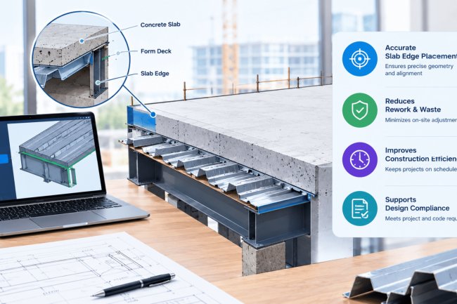
Pour sequencing is frequently treated as a contractor's logistical concern, but it is fundamentally a structural engineering problem. The wet concrete placed on an unshored composite deck system applies a dead load that the deck and supporting joists or beams must resist in their non-composite state. Until the concrete cures and composite action is engaged, the steel section alone carries all construction-phase loads.
Construction-Phase Reality
Before Composite Action,
the Steel Carries the Pour
During Placement
Non-Composite
→
After Cure
Composite Action
Temporary Structural Condition
The Non-Composite Construction Phase
During placement, the steel deck acts as formwork and the steel framing carries 100% of the wet concrete weight — typically 40–75 psf depending on slab thickness and deck depth. If the pour sequence concentrates load in a single bay while adjacent bays remain unloaded, differential deflection can crack fresh concrete at construction joints and compromise the bond between deck and concrete.
40–75
psf
Typical wet concrete construction-stage loading range identified in the design basis.
Before the concrete has developed strength and composite behavior, the deck and supporting steel framing must resist this load in their construction-stage condition.
Construction Load Components
Define the Full Construction-Phase Load
Wet concrete self-weight: 12.5 pcf × slab thickness (ft)
Deck self-weight: typically 2–3 psf for 18–20 gauge profiles
Composite Deck Coordination
Deck Layout Coordination: Setting the
Stage for Sequencing
Before a single cubic yard of concrete is placed, the deck layout itself must be coordinated to support an efficient and structurally valid pour sequence. Deck orientation, sheet end-lap location, side-lap fastener patterns, and support framing geometry all influence where construction joints can be placed and how the load is distributed during pouring.
COORDINATE
PRE-POUR COORDINATION
Deck Layout Dictates Where Construction Joints Can Be Placed and How Load Is Distributed During Pouring
Deck orientation, end-lap locations, side-lap fastener patterns, and framing geometry must all be coordinated before shop drawings are released for fabrication. End laps must align with support members with minimum 1½-inch bearing. Side-lap connections must maintain diaphragm integrity through construction joints. Irregular column grids and setbacks create natural pour bay boundaries that must be explicitly documented. Camber affects wet concrete depth and must be accounted for in volume calculations.
⟷
ORIENTATION & LAP LOCATION
Deck Orientation and Span Direction
Floor deck is typically oriented so that flutes run perpendicular to the primary support framing (joists or beams). This maximizes the composite deck's structural efficiency in the spanning direction. However, the orientation also dictates where end laps fall—and end-lap locations must align with support members, not occur mid-span.
End-lap alignment: Construction joints are typically placed at or near deck end laps, making lap location a key coordination input for the pour map. End laps must be consistently located at supports with a minimum 1½-inch bearing.
Documentation: Lap locations must be shown on the deck layout plan with clear field-of-application dimensions.
Structural efficiency: Perpendicular orientation maximizes composite deck spanning capacity.
DIAPHRAGM CONTINUITY
Side-Lap Fastener Patterns and Diaphragm Continuity
Side-lap connections (button-punches, screws, or puddle welds) provide continuity between adjacent deck sheets and are critical for diaphragm performance. When a construction joint interrupts a bay mid-pour, the fastener pattern must maintain diaphragm integrity through the joint.
EOR coordination: Detailers must coordinate with the EOR to ensure that fastener spacing specified on the structural drawings accounts for both the final composite condition and the intermediate diaphragm demands during construction.
Lateral systems: Particularly critical in buildings with lateral systems that rely on the floor diaphragm for load distribution.
Fastener types: Button-punches, screws, or puddle welds—selected based on diaphragm demand and deck profile.
⧉
POUR BAY BOUNDARIES
Framing Geometry and Pour Bay Boundaries
Irregular column grids, re-entrant corners, and setbacks create natural pour bay boundaries that must be explicitly documented. A pour bay that crosses a framing setback without accounting for the reduced beam capacity on one side can overload the smaller section during construction.
Early zoning: Deck layout drawings should zone the floor plate into pour bay regions early in the coordination process—ideally before shop drawings are released for fabrication.
Detail coordination: Edge pour strips, closure pours, and slab edge details must be properly detailed for each pour bay region.
Load accounting: Account for reduced beam capacity at setbacks to prevent overloading during construction.
⤢
CAMBER & VOLUME
Camber and Pre-Deflection Coordination
Cambered beams introduce a pre-deflection that affects wet concrete depth across a bay. A beam cambered 1½ inches over a 40-foot span will draw additional concrete toward midspan as it deflects under wet load, increasing the actual slab thickness—and thus the wet dead load—beyond what was assumed in the pour sequence load analysis.
Volume calculations: Detailers and planners must account for camber in volume calculations to prevent underestimating wet concrete demand.
EOR confirmation: Coordinate with the EOR to confirm the assumed wet concrete depth used in deck and beam design.
Ponding risk: Camber-induced deflection can create low points that attract additional concrete, increasing dead load and potentially amplifying deflection.
Deck Layout Coordination Checklist
✓ End-Lap Location End laps consistently located at supports with minimum 1½-inch bearing. Lap locations shown on deck layout plan with clear field-of-application dimensions.
✓ Side-Lap Fasteners Fastener spacing accounts for both final composite condition and intermediate diaphragm demands during construction. Coordinated with EOR for lateral system requirements.
✓ Pour Bay Zoning Floor plate zoned into pour bay regions early, before shop drawings released. Edge pour strips, closure pours, and slab edge details properly detailed for each region.
✓ Camber Accounting Camber accounted for in volume calculations. Wet concrete depth confirmed with EOR. Ponding risk evaluated and mitigated in pour sequence load analysis.
✓ Framing Setbacks Irregular column grids, re-entrant corners, and setbacks documented as natural pour bay boundaries. Reduced beam capacity at setbacks accounted for to prevent overloading.
✓ Construction Joint Alignment Construction joints placed at or near deck end laps. Fastener patterns maintain diaphragm integrity through joints. Pour map coordinated with lap locations.
CRITICAL COORDINATION
End Laps Must Align with Supports—Not Mid-Span
STRUCTURAL REQUIREMENT
✅
Correct Practice End laps consistently located at supports with minimum 1½-inch bearing. Lap locations shown on deck layout plan with clear dimensions. Construction joints placed at or near end laps.
⚠️
Common Error End laps occurring mid-span without adequate support. Insufficient bearing (less than 1½ inches). Lap locations not shown on deck layout plan. Construction joints misaligned with lap locations.
Detailers should confirm that end laps are consistently located at supports with a minimum 1½-inch bearing, and that lap locations are shown on the deck layout plan with clear field-of-application dimensions.
CAMBER EFFECT
Camber Draws Additional Concrete Toward Midspan
A beam cambered 1½ inches over a 40-foot span will draw additional concrete toward midspan as it deflects under wet load, increasing the actual slab thickness—and thus the wet dead load—beyond what was assumed in the pour sequence load analysis.
Coordination requirement Detailers and planners must account for camber in volume calculations and coordinate with the EOR to confirm the assumed wet concrete depth used in deck and beam design. Failure to account for camber can result in underestimating wet concrete demand, overloading beams during construction, and creating ponding conditions that amplify deflection.
The Deck Layout Coordination Principle
Before a single cubic yard of concrete is placed, the deck layout itself must be coordinated to support an efficient and structurally valid pour sequence. Deck orientation dictates where end laps fall—end laps must align with support members with minimum 1½-inch bearing, not occur mid-span. Side-lap fastener patterns must maintain diaphragm integrity through construction joints, particularly in buildings with lateral systems that rely on the floor diaphragm for load distribution. Irregular column grids, re-entrant corners, and setbacks create natural pour bay boundaries that must be explicitly documented—zone the floor plate into pour bay regions early, before shop drawings are released for fabrication. Cambered beams draw additional concrete toward midspan as they deflect under wet load—account for camber in volume calculations and coordinate with the EOR to confirm the assumed wet concrete depth used in deck and beam design. Deck layout coordination is not optional—it is the foundation of a safe, efficient, and structurally valid concrete placement sequence.
Concrete Placement Planning
Developing the Pour Sequence Plan
A pour sequence plan is a coordinated document — part structural check, part logistics map — that translates engineering constraints into actionable field instructions. It defines which bays are poured in which order, where construction joints fall, how much time must elapse between adjacent pours, and where temporary shoring is required. The plan should be developed jointly by the EOR, the structural steel fabricator/erector, and the concrete contractor before mobilization.
Pour Sequence Architecture
Engineering Constraints → Field Sequence
PRE-MOBILIZATION
Execution Framework
Four Steps From Structural Check to Pour Order
Establish the Load Envelope
The EOR calculates the maximum wet concrete load the deck and framing can sustain without shoring, including the construction live load per ASCE 37. This load envelope sets the maximum allowable pour area per sequence — typically expressed as a maximum bay count or square footage per pour event.
Load envelopes should be recalculated when the contractor proposes changes to concrete mix, which affects unit weight, or when slab thickness deviations are anticipated due to camber.
Identify Critical Bays and Constraints
Cantilever bays, transfer beams, long-span joists, and bays adjacent to open-web steel joist (OWSJ) systems with differing deflection characteristics are flagged as critical. These bays may require shoring, may dictate pour direction, or may need to be completed before or after adjacent bays to avoid differential settlement of the forming system.
CANTILEVER TRANSFER BEAM LONG-SPAN JOIST OWSJ TRANSITION
Lay Out Construction Joints
Construction joints in composite slabs require careful detailing. Joints must be located where the structural design allows a discontinuity in the slab — typically at the one-fifth to one-quarter point of the span to minimize the impact on flexural continuity.
Joint Detail
Surface preparation, reinforcement continuity, and joint type must be specified.
Deck Layout
Show whether the joint falls over support or within a span because the detail changes significantly.
Sequence for Symmetry and Load Balance
The preferred strategy is to pour bays symmetrically about the building's center of stiffness, alternating between opposite sides of a core or primary framing spine. This balances the wet load incrementally and limits differential deflection between poured and unpoured bays.
Checkerboard patterns — alternating poured and skipped bays — can reduce peak load on any single framing line but require careful joint detailing and re-inspection of the wet surface before the infill pours.
Sequence Visualization
Balance the Wet Load Around the Building Spine
Example Sequence Logic
1
SKIP
CORE
2
SKIP
SKIP
3
SPINE
4
SKIP
5
SKIP
CORE
6
SKIP
Alternating poured and skipped bays can reduce peak demand on individual framing lines while helping maintain a balanced placement sequence.
Coordination Ownership
One Plan, Three Primary Stakeholders
EOR
Structural load envelope, shoring, and joint requirements.
Steel Team
Deck, framing, access, and erection constraints.
Concrete Team
Placement logistics, sequence execution, and field coordination.
Final Planning Principle
Sequence the Pour Before the Concrete Arrives
A successful pour sequence plan connects structural capacity, critical-bay identification, construction-joint placement, shoring requirements, and load-balanced sequencing into one coordinated field document. The objective is not simply to determine where concrete goes first, but to control how the entire floor system responds as the wet load moves across the structure.
Concrete Construction Engineering
Shoring, Reshoring & Multi-Level Considerations
When shoring and reshoring requirements are not properly coordinated, elevated deck construction can quickly encounter structural overloads, schedule delays, and safety risks. Successful execution requires detailed load-path analysis, deck coordination, and engineered planning throughout every stage of the construction sequence.
When Shoring Is Required
Shoring becomes necessary whenever wet concrete loads, combined with construction live loads, exceed the available non-composite capacity of the deck and supporting framing. Common triggers include long-span composite beams with inadequate non-composite strength, slab-on-deck systems exceeding 5½ inches in thickness, and pours adjacent to recently placed bays that have not yet developed sufficient strength for load redistribution.
Shore spacing, capacity, and bearing conditions at both the shore head and base must be documented on engineered shoring plans and coordinated with deck layouts to prevent concentrated loads from punching through the deck system.
Reshoring in Multi-Story Systems
Upper-level slab pours often transfer loads through shores into lower floors that have not yet achieved full design strength. These temporary load paths must be analyzed by the Engineer of Record and included within the reshoring plan.
ACI 347 provides guidance regarding minimum concrete strength requirements before reshore removal, while the IBC requires licensed engineering oversight of the plan. Reshoring schedules must align directly with concrete strength gain and floor-by-floor construction sequencing.
Shore Layout Coordination With Deck
Shore heads must bear directly on deck ribs rather than within flute valleys to prevent localized buckling or punching failures. On wide-rib profiles such as 3-inch composite deck, a poorly positioned shore can impose concentrated loads between 2,000 and 4,000 pounds on unsupported steel deck.
All shore layouts should be cross-referenced against deck placement drawings, and field verification should occur before concrete placement begins. Mudsills at the base must be sized adequately to distribute loads to the supporting slab below within allowable bearing stress limits.
Construction Load Transfer Sequence
①
Deck & Framing
Verify non-composite capacity before placement.
②
Install Shores
Position heads on deck ribs and verify mudsill bearing.
③
Concrete Placement
Load transfers safely through the engineered shore system.
④
Reshore & Remove
Remove supports only after required strength is achieved.
Critical Engineering Reminder
Shoring and reshoring decisions directly affect structural safety, slab performance, and project schedule. All temporary load paths, shore bearing locations, concrete strength milestones, and removal sequences must be coordinated among the Engineer of Record, deck detailer, contractor, and testing agency before construction progresses to the next floor level.
Field Coordination • Pour Sequencing • Construction Documentation
Field Coordination, Documentation & Key Takeaways
Even the most carefully engineered pour sequence plan is only as effective as the field coordination that implements it. The gap between the drawing set and the jobsite is where sequencing failures most often occur — a missed cold joint, an unshored bay, or a pump truck positioned over an uncured pour can compromise months of planning.
From Drawing Set to Jobsite
Engineering Intent Must Survive
Field Execution
Approved Plan
→
Field Coordination
→
Controlled Pour
Jobsite Controls
Critical Field Coordination Points
Pre-pour inspection
Pre-pour inspection: Structural engineer or inspector should verify deck fastening, shear stud installation, shoring layout, and reinforcement placement before concrete placement begins in each pour zone.
Pump truck and buggy positioning
Pump truck and buggy positioning: Equipment loads must be evaluated against the non-composite deck and framing capacity. Pump truck outrigger loads can exceed 50,000 lbs and must be positioned over primary structure, not mid-span on deck.
Concrete delivery rate
Concrete delivery rate: The rate of pour must be controlled to prevent wet concrete from accumulating beyond the design load in any bay before it can spread. A maximum pour rate (in cy/hr) should be specified on the pour plan.
Weather and temperature monitoring
Weather and temperature monitoring: Cold weather pours require protection measures that affect curing time and thus the timing of subsequent pours. Hot weather pours increase bleed water and may affect construction joint bond. Both must be addressed in the pour plan.