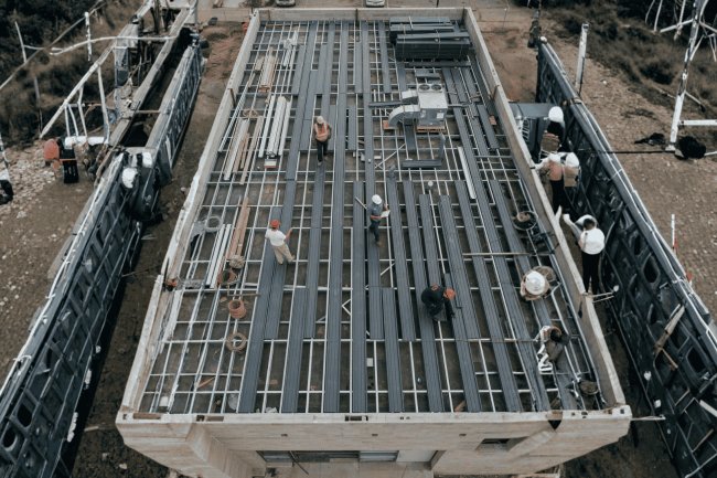
Understanding Single-Span and Multi-Span Deck Layouts
A focused guide for structural engineers and detailers on how span configuration shapes load behavior, structural efficiency, and constructability in steel deck systems.

What Is a Span Layout — and Why Does It Matter?
Before gauge, profile depth, attachment patterns, or diaphragm design can be finalized, one foundational question must be answered: how many supports will each deck sheet span? Span layout directly influences moment distribution, reaction forces, deflection behavior, material efficiency, and the load tables that govern the design.
Span Layout Drives Structural Behavior
Single-Span Layout
• No continuity across supports
• Symmetrical reactions
• Maximum positive moment at midspan
• Simplest analysis method
• Lower structural efficiency per pound of steel
Multi-Span Continuous
• Negative moments develop at supports
• Positive moments occur at midspan
• Reduced deflection
• Improved load distribution
• Often permits lighter deck sections
How Span Layout Changes Forces
A single-span deck sheet bears load across one clear span, with both ends terminating at supports. Each sheet is structurally independent — no moment transfer occurs across supports. This simplicity makes single-span layouts predictable but also more demanding in certain contexts.
Each sheet acts alone, modeled as a simply supported beam. End reactions equal wL/2 and maximum moment equals wL²/8. No secondary effects or continuity conditions complicate calculations, making updates straightforward during design development.
Detailers must recognize these triggers in framing plans and flag them for the engineer of record.
Without continuity, the deck cross-section alone resists full positive moment. This often requires heavier gauge or deeper profiles compared to multi-span layouts. On long bays (8–10 ft+), the gauge penalty can drive value-engineering decisions toward framing reconfiguration.
SDI publishes simple-span allowable loads separately. Always confirm which column was referenced when checking submittals against structural documents.
Single-span decks simplify analysis but increase material demand. Recognizing when single-span conditions are unavoidable — and adjusting gauge or framing accordingly — is essential for both safety and cost efficiency.
Single-Span Deck: Behavior, Advantages & Limitations
Predictable Load Path
Common Situations That Force Single-Span Use
Key Limitation: Higher Demand, Heavier Gauge
SDI Load Tables
Key Insight
Continuity can reduce positive-span demand and improve structural efficiency, but only when the support regions, sidelaps, reinforcement, and span-table assumptions are detailed consistently.
Interior supports develop hogging moment, placing the deck top flange in tension. Composite floors require coordination of slab reinforcement and crack control in this region.
Continuous behavior depends on adjacent sheets sharing shear through their sidelap connections. Fastener spacing and type must reflect diaphragm stiffness and transfer demand, not gravity loading alone.
Two-span and three-or-more-span cases have different moment distributions. A table for one condition cannot be substituted for the other.
The outer bays and center support govern according to the two-span coefficients. Verify the actual sheet layout before selecting capacity.
Additional continuity changes moment distribution and may reduce interior positive moment, subject to the table’s stated assumptions.
Missing support continuity, cut sheets, interrupted sidelaps, or altered sheet direction can eliminate the assumed structural behavior.
Multi-span deck is efficient only when the structural model, span-table selection, sidelap connections, support reinforcement, and field installation all describe the same continuous system.
Multi-Span Continuous Deck: Efficiency & Detailing Discipline
Negative Moment at Supports
Sidelap Fastening
Two-Span vs. Three-Span
Span-Condition Discipline
Coordination Checklist
The Continuity Principle
The choice between single-span and multi-span deck layouts depends on the actual framing, erection sequence, deflection behavior, and material efficiency of each zone. A disciplined review prevents detailers from applying one configuration across conditions that are not truly equivalent.
Regular framing and continuous supports make multi-span layouts easier to standardize. Irregular bay widths, varying column grids, skewed geometry, or inconsistent sheet-end conditions can force individual bays back to single-span behavior.
Continuity depends on sheet ends overlapping across common supports. On phased projects, coordinate with the erector to determine where laps can actually occur and identify zones where construction sequencing creates single-span conditions.
Multi-span continuity can reduce live-load deflection, which can benefit floor systems. Roof applications require additional attention because support continuity may create upward curvature and interior low points that influence ponding behavior.
Multi-span continuity may allow a lighter deck gauge where the applicable span tables support it. Compare single-span and continuous conditions before finalizing the specification so material savings can be identified during design rather than after bidding.
Review every span condition.
Verify erection and sheet laps.
Select the correct load condition.
Balance capacity and material cost.
Apply the configuration check to every deck zone, not just the typical bay. Mapping the full floor or roof condition before standardizing the gauge prevents span-layout errors and gives the detailer an opportunity to identify meaningful optimization opportunities before shop drawings are released.
Choosing the Right Configuration: Decision Factors for Detailers
Four Questions Before You Standardize
What Should Drive the Configuration?
Bay Geometry and Support Spacing
Construction Sequence and Erection Order
Camber and Deflection Criteria
Gauge Optimization and Material Cost
From Framing Review to Gauge Selection
Check Geometry
Confirm Sequence
Apply SDI Table
Optimize Gauge
Span configuration drives nearly every downstream steel deck decision. From load-table selection and gauge optimization to diaphragm capacity and attachment requirements, accurate span-layout definition is one of the highest-value activities in the entire deck design process.
Walk the framing plan and verify actual deck continuity. Sheet end locations, construction phasing joints, expansion joints, large openings, and perimeter framing often create isolated simple-span zones inside seemingly continuous deck layouts.
Simple-span, two-span continuous, and three-span-or-more continuous tables are separate structural conditions. Using the wrong load table is not conservative design. It is a specification error frequently identified during deck submittal review.
Continuous behavior and diaphragm strength depend on side-lap connections. Structural drawings, specifications, and shop drawings must all define identical fastening assumptions to ensure the design intent is actually achieved in the field.
Multi-span continuity often permits lighter deck gauges while maintaining equivalent performance. Capturing this opportunity during design development can generate meaningful material savings without changing project scope.
The actual span condition must be resolved during design, documented in the contract drawings, verified in submittals, and maintained throughout erection. If continuity is assumed but not delivered, the structural assumptions behind the deck design no longer apply.
Detailers who identify true span conditions, coordinate continuity requirements, select the correct SDI load tables, and leverage continuity for optimization create safer designs, cleaner submittals, lower material costs, and fewer field corrections. Span layout is one of the highest-leverage decisions in steel deck design.
Key Takeaways for Span-Layout Decisions
One Decision. Multiple Consequences.
Identify the True Span Condition
Match the Correct SDI Table
Coordinate Side-Lap Fastening
Use Continuity to Optimize Gauge
Span Layout Validation Process
Span Layout Must Survive Every Project Phase
Span Layout Is a Design Decision, Not a Construction Decision
Own the Span Layout Early
What's Your Reaction?