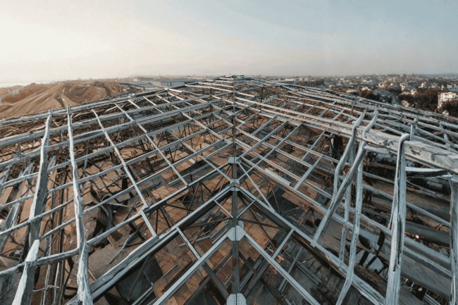
Floor Deck Bearing Coordination on Structural Steel Beams
A technical deep-dive into the critical interface between metal floor deck and structural steel beams — covering minimum bearing lengths, detailing tolerances, erection sequencing, and coordination pitfalls that every structural engineer, steel detailer, and construction coordinator must understand to deliver safe, code-compliant floor systems.
Why Bearing Coordination Is a High-Stakes Detail
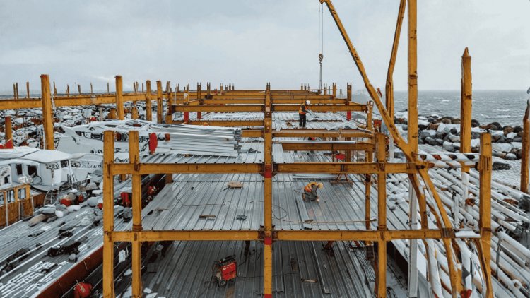
The bearing zone where metal floor deck rests on a structural steel beam is one of the most critical interfaces in a floor system. It is the location where gravity loads leave the deck and enter the structural frame, while simultaneously absorbing fabrication tolerances, erection variation, deck manufacturing tolerances, and installation sequencing effects. Despite its importance, this zone is often represented by little more than a generic note, leaving one of the most structurally sensitive details vulnerable to field interpretation.
Every Floor Load Passes Through The Bearing Zone
The bearing condition influences structural stability during erection, concrete placement, diaphragm performance, composite action, and long-term floor reliability.
What Converges At The Bearing Zone?
Common Failure Risks
Insufficient Bearing Length
May cause deck end rotation, deck end-slip, localized distortion, and uplift under uneven construction loading.
Flange Width Mismatch
Corrugation geometry may create concentrated point-bearing rather than uniform support across the flange width.
Misaligned Sheet Laps
Reduces diaphragm continuity and weakens intended force transfer across support lines.
Shear Stud Conflicts
Flute orientation and stud layouts may compete for the same limited support area if not coordinated early.
The Bearing Load Path
Every gravity load within the floor system must successfully pass through this relatively small support interface.
Why This Gets Missed
Bearing coordination lives between disciplines. Structural engineers define framing. Deck detailers define sheet layouts. Fabricators define steel geometry. Erection teams manage final alignment. Because responsibility is fragmented, bearing-zone coordination often falls into a gap between drawing packages until a field conflict emerges.
The Coordination Gap
Tolerance Stack-Up At The Support
Best Practice For Successful Coordination
Bearing dimensions should never be assumed from manufacturer minimums alone. Verify beam flange width, deck profile geometry, stud placement requirements, connection hardware clearances, erection tolerances, and diaphragm demands together before detailing is released.
SDI-DDM04 establishes baseline bearing lengths: 1.5 inches at end supports and 3 inches at interior supports. These assume beams are plumb, deck sheets cut within ±½ inch, no significant camber, and welds placed within the bearing zone.
Real-world tolerances accumulate: beams may shift ±¼ inch, deck sheets vary ±¼ inch. At extremes, a nominal 1.5-inch bearing can shrink below 1 inch — unsafe and below code minimum. Experienced detailers add a “bearing adequacy pad” to account for this.
To preserve safety margins, structural notes often specify 2 inches minimum at end supports and 3.5–4 inches at interior supports. This ensures compliance even under worst-case tolerance accumulation and should be documented in shop drawings.
Never design to bare SDI minimums on complex framing or wide spans. Always verify bearing adequacy against tolerance accumulation across beam position, deck cut length, and erection plumb to ensure structural safety.
Minimum Bearing Length: Code Baseline vs. Field Reality
Code-Referenced Minimums
Tolerance Stack-Up in Practice
Conservative Allowance
Key Insight
Bearing-zone quality depends on more than minimum support length. Deck corrugation, flute direction, overlapping sheets, stud placement, and beam flange width must work together to provide reliable bearing, attachment, and composite performance.
Floor deck may meet a supporting beam with flutes perpendicular or parallel to the beam. Perpendicular flute orientation is common with composite beams using shear studs, while parallel orientation is more common at edges and certain girder conditions.
Deck contacts the flange primarily at flute valleys. Puddle weld locations and shear-stud placement must follow the actual flute geometry to prevent interference.
Broader flange contact can simplify bearing, but lap geometry and sheet-end attachment still require careful coordination.
Beam flange width sets the physical limit for achievable deck bearing. Narrow flanges can become critical when interior deck laps, fasteners, and tolerances all need to fit within the available support width.
A wider flange generally provides more physical room for bearing on either side of the web and more tolerance for detailing.
A narrower flange may leave little room for lapped sheets, fastening, and fabrication tolerances. Verify the actual framing dimensions carefully.
Never evaluate bearing length in isolation. Flute orientation, lap geometry, beam flange width, fastener locations, shear studs, and fabrication tolerances must be considered together. The safest detail is the one that preserves adequate bearing while allowing every required connection and composite-system component to fit within the actual support geometry.
Detailing the Bearing Zone: Geometry, Flute Orientation & Lap Conditions
Flute Orientation at the Beam
Valley Contact
Uniform Contact
Beam Flange Width Adequacy
Even the most accurately detailed deck package can fail in the field if installation sequencing is poorly managed. The performance of the deck-to-beam interface depends not only on design dimensions but also on erection tolerances, beam alignment, camber control, bundle placement, fastening sequence, and field verification procedures. Successful projects treat erection sequencing as a structural quality-control process rather than a simple installation activity.
Bearing, diaphragm performance, composite action, and construction safety all depend on how the deck installation sequence is executed in the field.
Beam plumbing and final alignment should be completed before deck installation begins within a bay. Residual beam sweep, lean, or erection tolerances can shift the effective bearing location by 1/2 inch or more, significantly reducing available bearing length and consuming the tolerance assumed during detailing.
Heavily cambered beams can alter support geometry near beam ends. Although camber is intended to offset dead-load deflection, excessive camber may reduce the effective level bearing surface available for deck support.
Deck bundles should be placed only at locations approved for the anticipated installation loads. Unattached or partially fastened deck panels are particularly vulnerable during staging activities and should never be overloaded beyond their documented unshored capacity.
Initiating fastening from the beam centerline and progressing outward helps prevent sheet buckling and unwanted distortion during installation.
End fasteners at bearing zones should be installed during the same work shift that the deck sheets are placed. Delayed fastening can expose deck panels to wind uplift, construction traffic movement, end-slip, and accidental displacement before the support connection is secured.
The most successful deck installations utilize a structured coordination process involving the Structural Engineer of Record (SER), steel fabricator, deck supplier, and installation crew before large-scale installation begins.
Review bearing zones, support geometry, installation sequencing, and project-specific constraints.
Confirm bearing dimensions match across structural, deck, and fabrication drawings.
Validate installation methods before progressing to full-floor production.
Floor deck performance depends as much on field execution as on design calculations. Proper beam alignment, camber verification, load staging, fastening sequence, and formal coordination reviews ensure that bearing zones perform exactly as intended. A disciplined protocol consisting of a pre-installation review, drawing cross-check, and first-bay inspection prevents the vast majority of field conflicts before they require expensive remediation. In modern steel construction, successful deck installation is the result of proactive coordination, not reactive problem-solving.
Erection Sequencing & Field Coordination Protocols
Proper Detailing Still Requires Proper Sequencing
Critical Sequencing Objectives
Beam Plumbing & Leveling
Camber Verification At Mid-Span
Deck Bundle Placement & Load Staging
Recommended Fastening Sequence
Same-Shift End Fastener Installation
Formal Coordination Protocol
Three Mandatory Coordination Checkpoints
Pre-Installation Review
Shop Drawing Cross-Check
First-Bay Inspection
Why These Checkpoints Matter
Sequencing Is A Structural Quality-Control Process
Recurring deck-to-beam bearing failures can be addressed before fabrication and erection by identifying the failure mechanism, assigning a preventive control, and verifying the condition in both the shop drawings and field.
Deck sheets can move longitudinally under wet-concrete or construction loading when puddle welds are delayed, omitted, or placed away from effective bearing valleys.
Build a deliberate margin above the governing minimum where the structural design permits and require a field measurement at the first bay of each deck zone before production proceeds.
Shear studs placed without considering deck flute geometry can interfere with proper deck seating or create unacceptable welding conditions. The stud layout should be reviewed directly against the deck profile before erection.
Overlay the shear stud layout with the actual flute pattern and identify permitted and prohibited placement zones.
Confirm installed deck geometry remains consistent with the stud locations before proceeding with composite construction.
Missing or misplaced lap fasteners at interior supports can interrupt the intended diaphragm load path and reduce lateral force resistance.
Bearing problems are easiest to prevent when they are treated as a coordinated design-and-installation issue. Establish the required bearing condition, coordinate deck and connection geometry in the shop drawings, verify the first installed bay, and secure the deck before construction loading begins.
Common Bearing Failures & How to Prevent Them
End-Slip Under Construction Load
Design Margin + First-Bay Verification
Shear Stud-Deck Interference
Diaphragm Discontinuity at Laps
Four Practices to Build Into Every Project
What's Your Reaction?