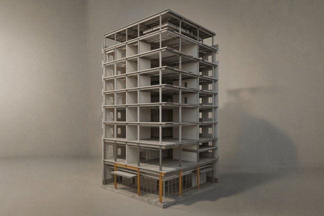
Roof Deck Edge Conditions at Building Perimeters
A technical deep-dive into the structural detailing, load transfer, and waterproofing interface requirements at the most vulnerable zone of any low-slope roof assembly — the perimeter edge.
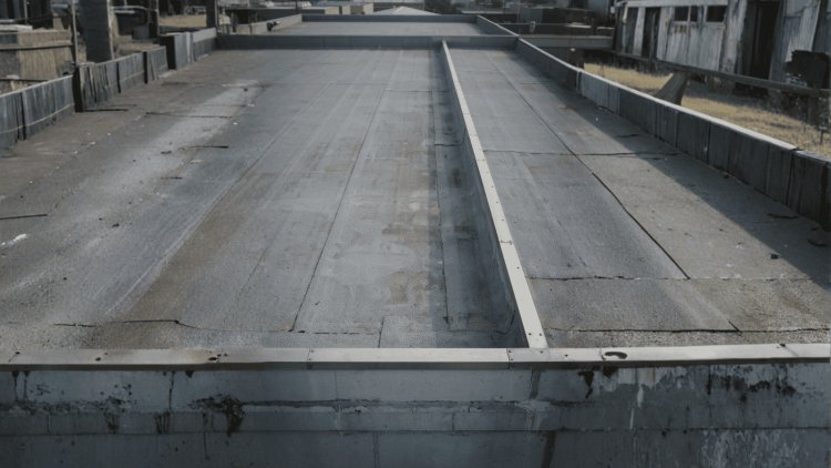
Why Perimeter Edge Conditions Demand Specialized Attention
The roof perimeter is one of the most technically complex zones in any building. Structural framing, roof deck, insulation, membrane systems, edge metal, facade components, and waterproofing assemblies all intersect within a relatively small area. Because these systems have different performance requirements, tolerances, and movement characteristics, perimeter conditions demand significantly more engineering attention than typical field-of-roof details.
More Systems Intersect Here Than Anywhere Else On The Roof
The perimeter edge is where structural performance, weather protection, architectural requirements, and construction tolerances all converge into a single coordinated detail.
Why Perimeter Conditions Are Different
Maximum Wind Loads Occur At The Perimeter
Enhanced attachment patterns, stronger edge securement, and more rigorous detailing are often required because perimeter uplift demands significantly exceed interior roof loading conditions.
Perimeter Detailing Priorities
Selecting the correct perimeter edge detail type is a structural decision first and a waterproofing decision second. The four primary configurations encountered on low-slope commercial roofs with metal deck substrates are: perimeter beam with roof edge metal (no parapet), parapet wall condition, gravel stop / fascia edge at elevated deck, and step condition / roof-to-wall transition. Each configuration has distinct structural requirements, wind load resistance criteria, and connection details that must be verified before fabrication and installation.
The deck terminates directly over the perimeter beam or spandrel member. A continuous steel angle or hat channel is welded or fastened to the beam to provide a substrate for edge metal flashings.
The deck terminates at or slightly past the interior face of the parapet. A continuous nailer, blocking member, or structural steel angle anchored to the parapet supports the base flashing turn-up.
Used on elevated mechanical platforms or roofs where the deck projects beyond the structural frame to form a fascia. The cantilevered deck ribs carry both dead load of roofing materials and uplift.
Occurs when a roof deck abuts a taller adjacent wall—common in multi-level roofs and penthouse conditions. The deck edge must be positively anchored against uplift.
Standard for wind design of metal edge systems (gravel stops, fascias, copings) used with low-slope roofing. Specifies test methods (ANSI/SPRI WDS-1) for determining wind load resistance of edge metal systems. Requires edge metal systems to be tested and labeled for specific wind pressures. Designer must select edge metal rated for project's calculated wind pressures per ASCE 7.
FM Global standards for wind uplift resistance of roof edge systems (FM 4435) and roof coverings (FM 4470). FM 4435 specifies test protocol for edge metal systems under wind uplift and outward pressure. FM Approvals Class 1 edge systems must pass FM 4435 testing. Designer must specify FM-approved edge systems for FM-insured buildings, rated for project's wind zone and building height.
Edge metal systems experience both uplift (vertical) and outward-acting (horizontal) wind pressures simultaneously. ANSI/SPRI ES-1 and FM 4435 test protocols apply combined loading to simulate real wind events. Designer must verify angle fastener pattern and weld sizing can resist combined uplift and outward-acting wind pressure on fascia system. Fasteners and welds sized for uplift alone will fail under combined loading.
For perimeter beam with roof edge metal (no parapet) condition: structurally, the designer must verify that the angle fastener pattern and weld sizing can resist the combined uplift and outward-acting wind pressure on the fascia system per ANSI/SPRI ES-1 or FM 4435/4470 criteria. This is the most common edge detail on commercial low-slope roofs and the most frequently under-verified for wind load resistance.
In seismic design categories C through F, relative story drift between the roof deck and adjacent taller wall can impose significant displacement demands on the flashing assembly. The gap between deck end and wall must be flashed with a reglet or through-wall flashing system that accommodates both vertical and horizontal differential movement.
Flashing system must accommodate both vertical differential movement (wall settling or heaving relative to deck) and horizontal differential movement (story drift perpendicular to wall). Reglet or through-wall flashing systems with slip joints, expansion joints, or flexible membrane components are required. Rigid flashing will crack or pull away under seismic displacement.
The deck edge must be positively anchored against uplift even in seismic conditions. Uplift anchors must not interfere with flashing system's ability to accommodate differential movement. Coordinate structural anchorage details with flashing details before fabrication. Seismic anchors that penetrate flashing must be sealed with flexible, movement-capable sealants.
Deck end bearing seats undersized or not verified. Results in deck end rotation under load, fastener pullout, and edge metal detachment. Designer must detail and verify deck end bearing—minimum 1.5" at end bearings per SDI.
Parapet anchorage not evaluated for overturning moment, particularly at corners where two-way load transfer occurs. Results in parapet cracking, base flashing failure, and water infiltration. Structural engineer must evaluate parapet anchorage for parapets taller than 18–24 inches.
Cantilevered deck ribs not checked for section properties, attachment at last interior support not sized for full cantilever reaction. Results in cantilever failure under uplift, deck rib buckling, and edge metal detachment. This condition is among the most frequently under-detailed in practice.
Flashing system does not accommodate differential movement, especially in seismic design categories C through F. Results in flashing cracks, reglet pullout, and water infiltration at wall-to-roof transition. Use reglet or through-wall flashing that accommodates vertical and horizontal movement.
Fasteners or welds sized for uplift alone, not combined uplift + outward pressure per ANSI/SPRI ES-1 or FM 4435/4470. Results in edge metal detachment during wind events. Verify angle fastener pattern and weld sizing for combined loading.
Deck-to-wall connections not thermally independent, creating thermal bridges at perimeter. Results in condensation, mold, and energy loss. Deck-to-wall connections should remain thermally independent of the wall where possible while still accommodating diaphragm shear.
The four primary configurations each have distinct structural requirements that must be verified before fabrication and installation. Wind load resistance, diaphragm shear, cantilever capacity, and seismic movement accommodation are the critical structural checks.
Selecting the correct perimeter edge detail type is a structural decision first and a waterproofing decision second. The four primary configurations encountered on low-slope commercial roofs with metal deck substrates are: perimeter beam with roof edge metal (no parapet), parapet wall condition, gravel stop / fascia edge at elevated deck, and step condition / roof-to-wall transition. Perimeter beam with roof edge metal (no parapet): the deck terminates directly over the perimeter beam or spandrel member; a continuous steel angle or hat channel is welded or fastened to the beam to provide a substrate for edge metal flashings; structurally, the designer must verify that the angle fastener pattern and weld sizing can resist the combined uplift and outward-acting wind pressure on the fascia system per ANSI/SPRI ES-1 or FM 4435/4470 criteria; the deck end bearing must be detailed and verified—undersized bearing seats cause deck end rotation under load. Parapet wall condition: the deck terminates at or slightly past the interior face of the parapet; a continuous nailer, blocking member, or structural steel angle anchored to the parapet supports the base flashing turn-up; parapets taller than 18–24 inches introduce significant overturning moment at their base—the structural engineer must evaluate masonry or metal stud parapet anchorage to the roof framing, particularly at corners where two-way load transfer occurs; deck-to-wall connections must accommodate in-plane diaphragm shear while remaining thermally independent of the wall where possible. Gravel stop / fascia edge at elevated deck: used on elevated mechanical platforms or roofs where the deck projects beyond the structural frame to form a fascia; the cantilevered deck ribs carry both dead load of roofing materials and uplift, requiring a careful check of deck profile section properties in the cantilever span; attachment to the spandrel beam at the last interior support must develop the full cantilever reaction, and welds or power-actuated fasteners must be sized accordingly; this condition is among the most frequently under-detailed in practice. Step condition / roof-to-wall transition: occurs when a roof deck abuts a taller adjacent wall—common in multi-level roofs and penthouse conditions; the deck edge must be positively anchored against uplift, and the gap between deck end and wall must be flashed with a reglet or through-wall flashing system that accommodates both vertical and horizontal differential movement; this condition is especially critical in seismic design categories C through F, where relative story drift can impose significant displacement demands on the flashing assembly. Each configuration has distinct structural requirements—wind load resistance per ANSI/SPRI ES-1 or FM 4435/4470, diaphragm shear accommodation, cantilever capacity verification, and seismic movement accommodation—that must be verified before fabrication and installation. Structural verification failures discovered after installation cost exponentially more to fix than structural verification failures caught before fabrication.
Structural Edge Detail Types: Anatomy and Engineering Criteria
Perimeter Beam with Roof Edge Metal (No Parapet)
• Deck terminates directly over perimeter beam or spandrel member
• No parapet wall present
• Continuous steel angle or hat channel welded or fastened to beam
• Angle/hat channel provides substrate for edge metal flashings
• Edge metal fascia system attached to angle substrate
• Verify angle fastener pattern can resist combined uplift and outward-acting wind pressure on fascia system
• Verify weld sizing can resist combined uplift and outward-acting wind pressure on fascia system
• Design per ANSI/SPRI ES-1 or FM 4435/4470 criteria
• Deck end bearing must be detailed and verified
• Undersized bearing seats cause deck end rotation under loadParapet Wall Condition
• Deck terminates at or slightly past interior face of parapet
• Continuous nailer, blocking member, or structural steel angle anchored to parapet
• Nailer/blocking/angle supports base flashing turn-up
• Parapet wall extends above roof surface
• Base flashing turns up along parapet face
• Parapets taller than 18–24 inches introduce significant overturning moment at their base
• Structural engineer must evaluate masonry or metal stud parapet anchorage to roof framing
• Particularly critical at corners where two-way load transfer occurs
• Deck-to-wall connections must accommodate in-plane diaphragm shear
• Deck-to-wall connections should remain thermally independent of wall where possibleGravel Stop / Fascia Edge at Elevated Deck
• Used on elevated mechanical platforms or roofs
• Deck projects beyond structural frame to form fascia
• Cantilevered deck ribs extend past last support
• Gravel stop or fascia edge metal at cantilever end
• Common on mechanical penthouse roofs, equipment platforms
• Cantilevered deck ribs carry both dead load of roofing materials and uplift
• Careful check of deck profile section properties in the cantilever span required
• Attachment to spandrel beam at last interior support must develop full cantilever reaction
• Welds or power-actuated fasteners must be sized accordingly
• This condition is among the most frequently under-detailed in practiceStep Condition / Roof-to-Wall Transition
• Roof deck abuts taller adjacent wall
• Common in multi-level roofs and penthouse conditions
• Vertical wall rises above roof surface
• Gap between deck end and wall must be flashed
• Differential movement between deck and wall must be accommodated
• Deck edge must be positively anchored against uplift
• Gap between deck end and wall must be flashed with reglet or through-wall flashing system
• Flashing system must accommodate both vertical and horizontal differential movement
• Especially critical in seismic design categories C through F
• Relative story drift can impose significant displacement demands on flashing assemblyEdge Detail Comparison: Structural Requirements by Configuration
Edge Detail Type
Primary Load Path
Critical Structural Check
Design Standard
Common Failure Mode
Perimeter Beam (No Parapet)
Deck → Angle/Hat Channel → Perimeter Beam → Column
Angle fastener pattern and weld sizing for combined uplift + outward wind pressure
ANSI/SPRI ES-1, FM 4435/4470
Undersized bearing seats cause deck end rotation
Parapet Wall
Deck → Nailer/Blocking/Angle → Parapet → Roof Framing
Parapet anchorage to roof framing (overturning moment at base), deck-to-wall diaphragm shear
ASCE 7, TMS 402 (masonry), AISI (metal stud)
Parapet overturning at corners (two-way load transfer)
Gravel Stop / Fascia (Elevated)
Cantilevered Deck → Last Interior Support → Spandrel Beam → Column
Deck profile section properties in cantilever span, attachment at last interior support for full cantilever reaction
SDI, AISI, deck manufacturer load tables
Most frequently under-detailed; cantilever failure under uplift
Step Condition / Roof-to-Wall
Deck → Positive Uplift Anchor → Adjacent Wall / Roof Framing
Positive uplift anchorage, flashing system accommodation of vertical + horizontal differential movement
ASCE 7 (seismic), ANSI/SPRI ES-1
Flashing failure from story drift (seismic categories C–F)
Wind Load Resistance Criteria: ANSI/SPRI ES-1 and FM 4435/4470
Seismic Considerations: Step Condition in Seismic Design Categories C Through F
Common Under-Detailed Conditions: Lessons from Field Failures
Perimeter Beam: Undersized Bearing
Parapet: Overturning at Corners
Gravel Stop: Cantilever Under-Design
Step Condition: Rigid Flashing
All Conditions: Fastener/Weld Under-Sizing
All Conditions: Thermal Bridging
Selecting the Correct Perimeter Edge Detail Type Is a Structural Decision First and a Waterproofing Decision Second
The Edge Detail Principle
AISC and SDI standards require a minimum 1½-inch bearing length for roof deck supports. At perimeter beams, tolerances can consume this margin. Designers must note minimum bearing requirements and detail flange widths to ensure adequate seating. For decks terminating flush with exterior beams, continuous welds or closely spaced mechanical fasteners at the end rib are essential to resist uplift and lateral rotation.
ASCE 7 defines roof zones: Field (Zone 1), Perimeter (Zone 2), and Corner (Zone 3). Perimeter zones extend 10% of the least horizontal dimension or 40% of mean roof height. Within these zones, fastener spacing must tighten — often shifting from 36/4 in the field to 18/3 or 12/4 at the perimeter. Structural drawings must clearly call out these intensified patterns with dimensioned boundaries.
The perimeter beam acts as the diaphragm chord, carrying net tension or compression from diaphragm moment gradients. Deck-to-beam connections must transfer both uplift and in-plane shear simultaneously. Collector forces parallel to deck span transfer through ribs as axial loads — requiring dedicated structural connections at the perimeter, not reliance on edge flashing. At re-entrant corners, chord reversals and stress concentrations demand supplemental reinforcing angles or continuous welded connections.
Perimeter deck attachment is a structural driver, not a detail to be generalized. Bearing length, intensified fastening, and chord/collector continuity must be explicitly detailed to ensure diaphragm performance and resistance to uplift forces.
Deck Attachment at Perimeter Zones
Bearing Length and End Conditions
Fastening Pattern Intensification
Diaphragm Chord and Collector Action
Key Insight
Structural capacity alone does not guarantee long-term roof performance. At the perimeter, membrane systems, flashing assemblies, edge metal, insulation, and structural framing must work together as a coordinated waterproofing system. Every detail must account for anticipated movement, drainage behavior, anchorage requirements, and fire-resistance provisions while maintaining a continuous watertight barrier throughout the life of the building.
The perimeter is where structural movement, thermal expansion, wind loading, membrane continuity, and drainage performance intersect. If one system moves and another cannot accommodate that movement, failures often begin at the edge.
Thermal expansion, contraction, and structural deflection are unavoidable. Details that do not allow controlled movement often experience membrane splitting, flashing separation, and edge-metal distortion.
Tall parapets, edge metal systems, and fascia assemblies can experience substantial wind demands. Fastener pullout values, substrate thickness, edge distance, and spacing requirements should be verified during detailing rather than after installation.
Long-span joist camber and dead-load deflection can change finished roof slopes after construction. Drainage evaluations should consider final loaded conditions rather than theoretical framing geometry alone.
Where waterproofing systems cross deck-to-wall transitions below grade or near grade level, membrane continuity must extend through the movement gap using approved bond-breaker materials and bridging membrane assemblies capable of accommodating differential movement.
Waterproofing failures frequently originate where structural design, roofing design, and envelope detailing overlap. Successful perimeter assemblies are achieved when movement, drainage, anchorage, fire protection, and membrane continuity are coordinated as one integrated system rather than separate disciplines.
Durable roof perimeter performance depends on much more than structural adequacy. Thermal movement accommodation, flashing anchorage, drainage design, ponding prevention, firestopping coordination, and membrane continuity must function together throughout the building lifecycle. When these systems are coordinated successfully, the roof edge becomes a resilient interface capable of resisting movement, weather exposure, wind loading, and long-term service demands without compromising watertight integrity.
Waterproofing Interface: Where Structural Detailing Meets Membrane Continuity
Waterproofing Success Depends On Movement Management
Four Waterproofing Coordination Areas
Rigid Details Fail When Buildings Move
Verify Fastener Capacity Before Construction
Account For Deflected Conditions
Gap Coordination Requirements
Below-Grade & Grade-Level Interfaces
Roof Leaks Often Begin At Coordination Points
Waterproofing Performance Is Engineered At The Edge
Successful perimeter edge details require deliberate multi-discipline coordination. Use this framework during design development and prior to issuing construction documents. Confirm wind uplift zones per ASCE 7, verify minimum bearing lengths at perimeter beams, size and detail continuous perimeter angle or nailer, design chord and collector connections, coordinate membrane base flashing height with parapet structural capacity, specify expansion joint locations, confirm roof deck slope at perimeter using deflected shape analysis, and coordinate firestopping at deck-to-wall gaps are the eight critical coordination items that define edge detailing success.
Confirm wind uplift zones per ASCE 7 and intensify deck attachment patterns explicitly on structural drawings with dimensioned zone boundaries. Zone boundaries must be drawn on the structural plan, not left to contractor interpretation. Applying field-zone fastening at perimeter—using standard 36/4 or 36/5 patterns throughout without intensifying at perimeter and corner zones—is the single most common uplift-related deck failure mechanism.
Verify minimum bearing lengths at perimeter beams after accounting for steel erection tolerances (±¼″ beam position is common). Undersized bearing seats cause deck end rotation under load. Minimum bearing lengths: 1.5" at end bearings, 3" at intermediate supports per SDI requirements. Account for beam position tolerances when detailing bearing seats.
Size and detail the continuous perimeter angle or nailer to resist combined uplift, fascia wind pressure, and base flashing anchor loads. The structural substrate for edge metal—the steel angle, nailer, and its connections to the framing—is a structural element. Leaving its design to a roofing specification without structural engineering review creates an uncontrolled load path that may not satisfy ANSI/SPRI ES-1 or FM requirements.
Design chord and collector connections to transfer in-plane diaphragm forces independently from the roofing edge metal system. Diaphragm forces must be transferred through structural elements (chords, collectors) without relying on edge metal flashings. Edge metal systems are not designed to resist in-plane diaphragm shear.
Coordinate membrane base flashing height with parapet structural capacity—taller flashings impose greater overturning moment at the parapet base. Parapets taller than 18–24 inches introduce significant overturning moment at their base. Structural engineer must evaluate masonry or metal stud parapet anchorage to the roof framing, particularly at corners where two-way load transfer occurs.
Specify expansion joint locations in edge metal at intervals per SMACNA, and detail membrane bridging at each joint. Edge metal expands and contracts with temperature changes. Without expansion joints, thermal movement causes buckling, fastener pullout, and seam failure. SMACNA specifies maximum intervals between expansion joints based on edge metal material and expected temperature range.
Confirm roof deck slope at perimeter using deflected shape analysis, not just dead-state framing geometry. Roof deck deflects under load (dead load, live load, snow). Deflected shape may reduce or reverse slope at perimeter, creating ponding. Analyze deflected shape under full load to confirm positive slope for drainage at perimeter. Ponding at perimeter accelerates corrosion and membrane degradation.
Coordinate firestopping at deck-to-wall gaps with membrane base flashing sequencing during construction. Firestopping must be installed before membrane base flashing to prevent membrane damage during firestopping installation. Sequence: (1) install deck, (2) install firestopping at deck-to-wall gaps, (3) install membrane base flashing over firestopping. Coordinate with fire protection engineer and roofing contractor.
Using standard 36/4 or 36/5 patterns throughout, without intensifying at perimeter and corner zones, is the single most common uplift-related deck failure mechanism. Zone boundaries must be drawn on the structural plan, not left to contractor interpretation. Perimeter and corner zones experience 2–3x higher wind pressures than field zones per ASCE 7. Fastener patterns must be intensified accordingly: 36/4 or 36/5 in field zones, 24/3 or 18/2 in perimeter zones, 12/2 or tighter in corner zones. Confirm wind uplift zones per ASCE 7 and intensify deck attachment patterns explicitly on structural drawings with dimensioned zone boundaries.
The structural substrate for edge metal—the steel angle, nailer, and its connections to the framing—is a structural element. Leaving its design to a roofing specification without structural engineering review creates an uncontrolled load path that may not satisfy ANSI/SPRI ES-1 or FM requirements. Size and detail the continuous perimeter angle or nailer to resist combined uplift, fascia wind pressure, and base flashing anchor loads. Structural engineer must verify angle fastener pattern and weld sizing per ANSI/SPRI ES-1 or FM 4435/4470 criteria. Edge metal contractor can select fascia profile and finish, but structural substrate must be engineered and shown on structural drawings.
Masonry parapets deflect and thermally move differently than the steel roof framing below. Without a properly detailed reglet or through-wall flashing with a slip plane, relative movement will crack or delaminate base flashings within the first few thermal cycles after construction. Deck-to-wall connections must accommodate in-plane diaphragm shear while remaining thermally independent of the wall where possible. Use reglet or through-wall flashing system with slip plane or expansion joint to accommodate differential thermal movement between masonry parapet and steel roof framing. Coordinate membrane base flashing height with parapet structural capacity—taller flashings impose greater overturning moment at the parapet base.
In SDC C and above, roof-to-wall step conditions must accommodate inter-story drift. The flashing detail must either be flexible enough to tolerate the calculated drift or must be on a structural element that moves with the deck—not the adjacent wall. This condition is especially critical in seismic design categories C through F, where relative story drift can impose significant displacement demands on the flashing assembly. The deck edge must be positively anchored against uplift, and the gap between deck end and wall must be flashed with a reglet or through-wall flashing system that accommodates both vertical and horizontal differential movement. Flashing system must accommodate both vertical differential movement (wall settling or heaving relative to deck) and horizontal differential movement (story drift perpendicular to wall).
Zone boundaries (field, perimeter, corner) explicitly drawn on structural drawings with dimensions. Not left to contractor interpretation. Fastener patterns specified for each zone.
Minimum bearing lengths (1.5" end, 3" intermediate) verified after accounting for ±¼″ steel erection tolerances. Bearing seats detailed to maintain minimum bearing even with worst-case beam position.
Continuous perimeter angle or nailer sized and detailed by structural engineer to resist combined uplift, fascia wind pressure, and base flashing anchor loads. Shown on structural drawings, not delegated to roofing spec.
Chord and collector connections designed to transfer in-plane diaphragm forces independently from roofing edge metal system. Edge metal not relied upon for diaphragm shear transfer.
Membrane base flashing height coordinated with parapet structural capacity. Parapets taller than 18–24" evaluated for overturning moment at base. Anchorage to roof framing verified by structural engineer.
Expansion joint locations in edge metal specified at intervals per SMACNA. Membrane bridging detailed at each joint. Thermal movement accommodated without buckling or fastener pullout.
Roof deck slope at perimeter confirmed using deflected shape analysis under full load, not just dead-state framing geometry. Positive slope for drainage verified at perimeter to prevent ponding.
Firestopping at deck-to-wall gaps coordinated with membrane base flashing sequencing. Firestopping installed before membrane base flashing to prevent membrane damage during firestopping installation.
Successful perimeter edge details require deliberate multi-discipline coordination. Use this framework during design development and prior to issuing construction documents. Confirm wind uplift zones per ASCE 7 and intensify deck attachment patterns explicitly on structural drawings with dimensioned zone boundaries—zone boundaries must be drawn on the structural plan, not left to contractor interpretation; applying field-zone fastening at perimeter using standard 36/4 or 36/5 patterns throughout without intensifying at perimeter and corner zones is the single most common uplift-related deck failure mechanism. Verify minimum bearing lengths at perimeter beams after accounting for steel erection tolerances (±¼″ beam position is common)—undersized bearing seats cause deck end rotation under load. Size and detail the continuous perimeter angle or nailer to resist combined uplift, fascia wind pressure, and base flashing anchor loads—the structural substrate for edge metal (the steel angle, nailer, and its connections to the framing) is a structural element; leaving its design to a roofing specification without structural engineering review creates an uncontrolled load path that may not satisfy ANSI/SPRI ES-1 or FM requirements. Design chord and collector connections to transfer in-plane diaphragm forces independently from the roofing edge metal system—diaphragm forces must be transferred through structural elements (chords, collectors) without relying on edge metal flashings. Coordinate membrane base flashing height with parapet structural capacity—taller flashings impose greater overturning moment at the parapet base; parapets taller than 18–24 inches introduce significant overturning moment at their base. Specify expansion joint locations in edge metal at intervals per SMACNA, and detail membrane bridging at each joint—edge metal expands and contracts with temperature changes; without expansion joints, thermal movement causes buckling, fastener pullout, and seam failure. Confirm roof deck slope at perimeter using deflected shape analysis, not just dead-state framing geometry—roof deck deflects under load; deflected shape may reduce or reverse slope at perimeter, creating ponding. Coordinate firestopping at deck-to-wall gaps with membrane base flashing sequencing during construction—firestopping must be installed before membrane base flashing to prevent membrane damage during firestopping installation. Common detailing errors to avoid: applying field-zone fastening at perimeter (most common uplift failure), delegating edge metal design entirely to roofing contractor (uncontrolled load path), ignoring differential movement at masonry parapets (thermal cracking), and omitting seismic drift accommodation at step conditions (seismic failure in SDC C+). Structural coordination verification before construction: all eight checklist items verified, all four common errors avoided, all ten best practices implemented. Coordination failures discovered after construction cost exponentially more to fix than coordination failures caught during design development.
Key Takeaways & Best Practices for Perimeter Edge Detailing
Design Coordination Checklist: Eight Critical Items
Common Detailing Errors to Avoid: Four Critical Mistakes
Applying Field-Zone Fastening at Perimeter
Delegating Edge Metal Design Entirely to Roofing Contractor
Ignoring Differential Movement at Masonry Parapets
Omitting Seismic Drift Accommodation at Step Conditions
Wind Uplift Zones per ASCE 7: Fastener Pattern Intensification
Zone Type
Location on Roof
Wind Pressure Multiplier (vs Field)
Typical Fastener Pattern
Zone Width (per ASCE 7)
Field Zone
Interior of roof, away from edges and corners
1.0x (baseline)
36/4 or 36/5 (36" spacing, 4 or 5 fasteners per sheet width)
Remainder of roof after perimeter and corner zones
Perimeter Zone
Along all roof edges, excluding corners
2.0–2.5x
24/3 or 18/2 (24" or 18" spacing, 2 or 3 fasteners per sheet width)
Width = 10% of building height or 40% of mean roof height, whichever is less, min 4 ft
Corner Zone
At roof corners (intersection of two perimeter zones)
2.5–3.0x
12/2 or tighter (12" spacing, 2 fasteners per sheet width)
Square zone at each corner, side length = same as perimeter zone width
Structural Coordination Verification: Pre-Construction Checklist
Best Practices Summary: Ten Principles for Successful Edge Detailing
The Coordination Principle
What's Your Reaction?