Roof Deck Layout Planning for Warehouse Buildings
A practical guide to structural coordination, load sequencing, and BIM-driven delivery for large-scale warehouse roof deck systems.
The Power of the Grid:
Geometry First
Before a single panel is ordered or a weld is specified, the foundational discipline of warehouse roof deck design is geometry. The structural bay grid is not merely a background reference — it is the load-path engine that governs every decision downstream.
Bay Geometry as the Structural Heartbeat
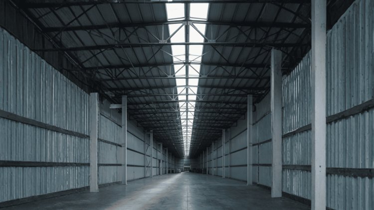
A standard 50 ft × 56 ft bay grid creates the rhythmic structural module from which all joist spacing and deck spanning decisions derive. This module defines center-to-center support intervals, dictates the maximum unbraced lengths, and sets the stage for efficient material utilization across repetitive bays. When the bay grid is established with discipline, every downstream coordination task becomes an exercise in pattern recognition rather than bespoke problem-solving.
Benefits of a Disciplined Bay Grid
Span Logic & Rib Orientation
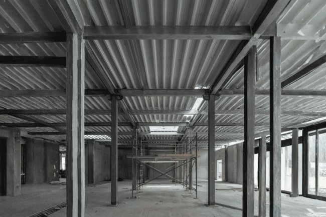
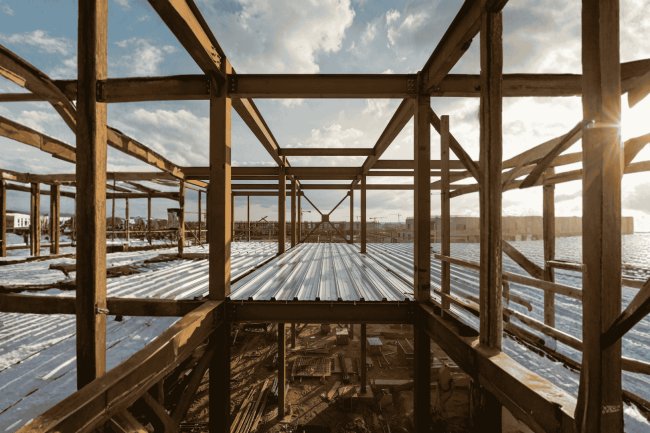
Deck ribs must span perpendicular to primary joist supports — this is not a preference, it is a structural imperative. Correct rib orientation ensures that loads travel efficiently along the intended load path, supports composite behavior where specified, and prevents eccentric bending at panel edges. Layouts that inadvertently allow ribs to run parallel to joists create bearing anomalies and diaphragm discontinuities that are difficult to resolve without costly field modifications.
Correct Load Path Logic
Strategic Profile Uniformity
Standardizing deck profiles and gauges across repetitive bays delivers compounding benefits throughout fabrication, installation, inspection, and project administration. Reserve non-standard gauges or profiles exclusively for locations where structural demand genuinely differs from typical conditions, such as edge bays, cantilevers, and transfer zones.
One Profile, Many Advantages
Specification Philosophy
Good Geometry Solves
Problems Before They Exist
The most economical warehouse roof deck system is rarely achieved through complicated detailing. It begins with disciplined geometry, proper rib orientation, and profile standardization. When the grid is right, the entire project benefits from simpler detailing, cleaner load paths, and more efficient execution.
Roof-deck coordination is a continuing validation loop. Bearing, construction-stage loading, shoring, pour sequence, and diaphragm attachments must be checked together from layout through installation.
Check every bearing location for the required bearing width and document the corresponding weld pattern or fastener schedule. Do not rely on idealized centerline geometry.
Before concrete cures, the deck may carry wet concrete, workers, equipment, localized stockpiles, and sequence-dependent pour pressures. This stage can govern strength, deflection, and shoring.
Sidelap fastening transfers shear between sheets and contributes to diaphragm resistance. Show fastener type, spacing, and pattern explicitly rather than leaving them to installer judgment.
A deck that works after curing may not be adequate during placement.
Every gauge decision should be supported by three confirmations: the deck bears on the real supports, it survives the actual construction sequence, and its fastening schedule transfers the required diaphragm forces.
The Coordination Loop: Performance & Loads
Verify Every Support
Govern the Pour Stage
Detail Diaphragm Fastening
The Three-Part Review Loop
Designing Only for the Final State
The Coordination Principle
Deck interruptions for equipment, skylights, stairs, and MEP risers require dedicated header framing to redistribute loads. Rib orientation at opening boundaries must be analyzed, as panels terminating at edges cannot rely on continuous rib support. Neglecting header design leads to localized deflection, cracked topping, and serviceability issues.
Pour stops and closure elements are structural components designed to resist hydrostatic pressure during pours. Re-entrant corners are especially vulnerable and require custom closures and bracing — generic details are insufficient. Explicit detailing of connections to framing is critical for perimeter integrity.
Consolidated, cross-referenced shop drawings validated against actual joist camber and support alignment prevent field-level rework. Without accounting for camber, deck panels arrive at incorrect elevations; without verified alignment, bearing widths fall short. Rigorous shop drawing review is the definitive shield against RFIs in warehouse deck projects.
Navigating the High-Risk Zones
Opening Management
Edge Termination Engineering
The RFI Shield: Coordinated Shop Drawings
For warehouse buildings characterized by repetitive structural bays, BIM is not simply a visualization tool — it is the authoritative coordination platform that connects design intent, fabrication data, and field installation into a single, synchronized workflow.
Engineers repeatedly detail similar bays, increasing effort and introducing inconsistency.
Typical bay properties are replicated consistently throughout the project using coordinated model logic.
The repetitive bay geometry of a warehouse is a BIM force multiplier. Model the typical bay once — with full profile geometry, gauge, fastener pattern, and bearing condition — then propagate those properties across all standard bays using array or copy logic. Reserve custom detailing efforts exclusively for atypical conditions: transfer zones, cantilevered edges, heavy mechanical equipment pads, and stair towers. This approach compresses modeling time while ensuring that typical conditions are never under-detailed.
Deep-profile roof deck ribs — particularly 3-inch and 3.5-inch corrugated profiles — create significant geometric conflicts with MEP systems routed near the structural plane. Without proactive clash detection, conduit runs, sprinkler mains, and HVAC ductwork are commonly found to intersect deck ribs mid-project, triggering costly rerouting and sequence disruptions. Running interference checks in the BIM model between deck rib geometry and all MEP routing before shop drawings are issued eliminates this class of surprise entirely.
The full value of a coordinated BIM model is only realized when its outputs directly drive fabrication and installation. Extract coordinated layout plans, panel schedules, and fastener zone maps directly from the model — do not manually redraft them from the model into separate drawings, as this reintroduces transcription error. When fabricators and field installers are working from model-extracted documents, the project's coordination chain remains unbroken from design through final pour.
The true power of BIM lies in maintaining a continuous, coordinated flow of information from engineering through fabrication and installation. When the model becomes the project's single source of truth, clashes are eliminated earlier, detailing becomes more consistent, and execution becomes substantially more predictable.
BIM as the
Source of TruthWhy Repetitive Warehouses Amplify BIM Value
Recreate Repeatedly
Model Once
How BIM Creates Project Alignment
Repetition as a Modeling Asset
Efficient Warehouse Modeling Strategy
Proactive Clash Detection
Digital Handoff & Trade Synchronization
Connected Project Workflow
Model-Derived Deliverables
BIM Is Not A Model.
It's The Coordination Chain.
Reliable roof-deck delivery is a coordination discipline. Structural design, fabrication, shop drawing review, trade interfaces, and installation sequencing must remain aligned from the first layout through the final pour.
Structural alignment, load validation, shop drawing review, and trade communication should run in parallel with design rather than follow it.
Zero-RFI execution comes from aligned documents, explicit zones, early trade involvement, and details that answer installer questions before installation begins.
Build the full roof-deck assembly in the BIM model before fabrication, then verify every critical condition on the coordinated print set before welding or installation.
Coordinate structural, deck, joist, framing, BIM, and concrete documents.
Distinguish interior, perimeter, collector, and enhanced fastening zones.
Size headers and engineer closures, pour stops, and edge details.
Confirm current drawings, bearing checks, shoring, pour sequence, and trade routing.
A successful roof deck does not call attention to itself after construction.
Build it in the model, verify it on the prints, coordinate it with the trades, and validate it during construction. The strongest warehouse roof deck is the one whose coordination work is complete before the field has to ask for it.
From Design Intent to Final Pour
Coordinate Continuously
Design for Zero RFIs
Model First, Print Verify
The Zero-RFI Checklist
Invisible in Service
The Final-Pour Principle
What's Your Reaction?