Design Considerations for Long- Span Steel Deck Areas
Long-span steel deck systems push structural performance to its limits — demanding precise engineering judgment at every stage of the design process. Whether you're detailing floor decks spanning 10 to 14 feet between joists or roof assemblies stretching across wide-open bays in warehouses, convention centers, or athletic facilities, the margin for error narrows significantly as span lengths increase. This presentation distills the key structural, constructability, and detailing considerations that practitioners must address when designing, specifying, or detailing steel deck in long-span applications.
Why Long-Span Deck Behaves Differently
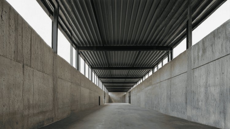
As span length increases, the deck transitions from a secondary component into a primary structural element.
The Structural Escalation Curve
What Begins to Govern?
Deflection increases with the fourth power of span length, making serviceability and construction-stage performance dominant concerns in long-span systems.
Long Span Changes the Rules
In long-span applications, the deck is no longer just a load-transfer surface. It becomes a primary structural member whose stiffness, stability, construction performance, and attachment design must all be evaluated carefully.
In long-span deck design, profile geometry is the single most impactful variable. Rib height, flange width, web thickness, and cross-sectional shape directly govern stiffness, span capacity, and deflection performance.
Deep roof deck profiles in the 4.5″–6″ range are used in arenas, hangars, and industrial buildings where purlins or joists may be spaced 6 to 10 ft apart. They provide superior stiffness and reduce deflection under snow and wind uplift loads.
Deck Profile Selection for Long-Span Applications
Deep Roof Deck
Long-span steel deck must be evaluated across multiple distinct load stages. Engineers and detailers must rigorously check construction-phase loading, which often governs, rather than focusing only on in-service conditions.
Wet concrete weighs ~150 pcf. Spread across a 14-ft unshored span, moment demands can exceed section capacity even at 16-gage profiles. Temporary shoring must be evaluated early, as placement affects joist sizing, slab edge forming, and sequencing.
Once composite action develops, the deck resists superimposed live loads. Long-term performance must meet deflection limits and vibration criteria, ensuring serviceability under office, assembly, or storage occupancy demands.
Long-span deck design requires holistic evaluation across construction and in-service phases. Ignoring temporary loads or overlooked combinations can lead to unsafe conditions, costly remediation, and compromised performance.
Critical load conditions in long-span design demand rigorous checks. By enforcing deflection limits, accounting for overlooked combinations, and planning shoring early, engineers ensure safety, serviceability, and resilience in steel deck systems.
Governing Load Stages in Steel Deck Design
Construction Phase
In-Service Phase
Deflection Limits to Enforce
Load Combinations Often Overlooked
Design Implications
In long-span systems, support details are not miscellaneous connections. They are critical structural components that govern load transfer, stability, and continuity.
Long-span deck develops larger support reactions. Increased seat lengths and proper bearing conditions help prevent deck-end deformation and loss of support engagement.
Fastener spacing, weld patterns, sidelaps, and diaphragm connections must be verified against actual shear demand rather than assumed from standard details.
Continuous spans improve stiffness and reduce positive moments, but continuity can only be credited when sheet layout, sidelaps, and support alignment are detailed accordingly.
Long-span deck capacity is determined not only by the panel itself, but by how effectively loads are transferred into the supporting structure.
Structural Detailing Requirements at Support Conditions
The Support Integrity Chain
Bearing Width
Attachment Design
Continuity Across Supports
Long-span steel deck projects succeed or fail in the detailing phase. The structural engineer’s design intent must be translated into constructable, inspectable shop drawings and erection documents that account for tolerances, sequencing, shoring access, and trade interfaces.
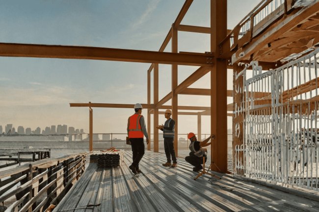
The construction sequence for long-span areas typically requires that structural steel framing — including primary beams, girders, and joists — be fully erected and connected before deck installation begins.
In phased construction or accelerated schedules, partial bay loading from wet concrete must be evaluated so incomplete frame conditions do not create unintended load paths through the deck.
Long-span deck zones benefit most from three-dimensional coordination. Clash detection between deep-profile deck ribs and MEP penetrations is critical, since higher rib depth reduces clear space below the slab and above the deck.
Require a deck-specific review milestone before concrete placement is authorized, and cross-reference final shop drawings against the structural engineer’s load assumptions before approval.
The workflow should stay consistent: design intent is set by the engineer, shop drawings translate it into layout and coordination, and field verification confirms shoring, bearing, and attachments before the pour. That sequence is what keeps long-span deck builds safe, buildable, and aligned with the original design basis.
Construction Sequence for Long-Span Deck
Coordination with Structural Sequence
BIM & Shop Drawing Review
What's Your Reaction?