Steel Deck Span Planning for Efficient Framing Systems
Steel Deck Span Planning for Efficient Framing Systems
Span planning is one of the most consequential decisions in steel deck design. Get it right, and you unlock a framing system that is structurally sound, cost-efficient, and straightforward to fabricate and erect. Get it wrong, and the ripple effects show up in deflection problems, added shoring, heavier joist schedules, and costly field corrections. This guide walks structural engineers and framers through the core principles, variables, and decision logic that drive effective steel deck span planning — from deck profile selection to support spacing, load assumptions, and coordination with the joist layout below.
Steel Deck Has a Strong Direction and a Weak Direction
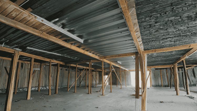
Corrugated steel deck behaves more like a series of miniature beams than a flat plate. The flute geometry creates high stiffness parallel to the ribs and lower stiffness perpendicular to them. Because of this, deck always spans across supports, perpendicular to the flute direction. Understanding this directional behavior is the foundation of every span calculation.
Direction Governs Performance
Deck Flutes
→
Span Direction
Span Continuity Creates Efficiency
Single Span
● Two supports ● Simplest behavior ● Highest positive bending demand ● Least efficient use of material
Double Span
● Three supports ● Reduced mid-span moments ● Lower deflection ● Approximately 25–35% greater capacity
Triple Span & Beyond
● Additional continuity ● Smaller gains in efficiency ● Most published span tables stop at three-span conditions
Why Multiple Spans Perform Better
Continuity allows bending moments to be shared between adjacent spans, reducing peak demand and improving structural efficiency.
What Actually Controls Allowable Span?
ALLOWABLE SPAN
Profile & Gauge
Applied Load
Deflection Limits
Attachments & Fasteners
Strength Doesn't Always Govern
Strength Limit
Deflection Limit
In many occupied floor systems, allowable deflection (L/360) governs span selection before flexural strength is fully utilized.
Common Design Limits
L/240
Construction Load Deflection
L/360
Occupied Floor Live Load
SPAN
Design Principle
Span Capacity Is a System Response, Not a Single Number
Allowable span emerges from the interaction of deck profile, gauge, loading, continuity, support conditions, and serviceability limits. Experienced deck designers do not ask, “How far can this deck span?” They ask, “Under what conditions can this deck safely and efficiently span?”
Span Efficiency
Deck Profile Selection and Span Efficiency
Choosing the right deck profile is the first structural lever in span planning. Each common rib depth occupies a different span range and load niche, so the goal is to match the profile to the joist spacing and load regime without overdesign.
1.5
1.5" Rib
The workhorse of composite floor decks. It typically spans 6 to 10 feet between joists or beams and works efficiently with 20 to 22 gauge material under typical office or residential loads.
Common gages: 20, 18, 16.
Ideal for closely spaced joist layouts.
Widely available with many published load tables.
2
2" Rib
The intermediate profile bridges light-duty composite deck and deeper structural profiles. It spans about 8 to 12 feet effectively and gives a useful increase in section modulus without a dramatic weight penalty.
Common gages: 20, 18.
Good balance of span and slab depth.
Can reduce joist count in moderate-load bays.
3
3" Rib
The deep deck profile is designed for longer joist or beam spacing, typically 10 to 15+ feet. Its higher moment of inertia supports spans that would need much heavier gage in a shallower profile.
Common gages: 18, 16.
Increases total floor assembly depth.
Reduces joist frequency, but concentrated loads need review.
MATCH
Match Profile to Load Regime
Pick the shallowest profile that satisfies span and load requirements so the framing schedule stays lean and overdesign is avoided.
VERIFY
Cross-Reference Published Tables
Always check the selected profile against the manufacturer’s published load tables for the exact span condition and loading assumptions before finalizing design.
Joist Spacing and Its Direct Impact on Span Planning
Optimizing Span-Spacing Tradeoffs
Steel deck span and joist spacing are inseparable variables. Every inch of spacing demands either heavier gage, deeper profile, or temporary shoring — each with cascading cost and coordination impacts. The best results come from balancing all three at the design stage, not fixing them in the field.
Reduce Joist Spacing
Bringing spacing back within deck capacity limits avoids overstressing thin-gage sheets. This option increases fabrication and erection scope but ensures compliance without temporary measures.
Upsize Gage or Profile
Moving from 22 gage to 20 gage, or switching to a deeper profile, increases stiffness and span capacity. This adds material cost but avoids operational disruption during concrete placement.
Add Temporary Shoring
Shoring beneath the deck during concrete placement prevents overstress but adds labor and disrupts operations. Best used as a fallback when spacing or gage cannot be adjusted.
Deck Capacity Checks
Deck span vs. allowable capacity under construction and in-service loads
Gauge and profile selection aligned with span spacing
Temporary shoring requirements documented if needed
Joist Manufacturer Coordination
Joist span vs. designation capacity under factored loads
End bearing and seat depth compatibility with beams/girders
Bridging requirements for longer spans and higher loads
Joist spacing decisions ripple across deck design, cost, and constructability. Explicit coordination with manufacturer tables and early optimization of span-spacing tradeoffs prevents costly field fixes and ensures structural reliability.
Steel Deck Design Fundamentals
Load Conditions That Drive Span Decisions
The Deck Must Survive Before It Can Perform
One of the most common misconceptions in steel deck design is assuming the final composite slab governs span selection. In reality, the most demanding condition often occurs during construction when the deck must independently support wet concrete, workers, equipment, and temporary loads before composite action develops.
The Structural Lifecycle of a Steel Deck
STAGE 01
Construction Phase
Bare steel deck carries its own weight, wet concrete, workers, equipment, and construction loads without composite assistance.
→
STAGE 02
Service Phase
Hardened concrete and deck act together as a composite structural system with significantly greater capacity.
Construction Loads Often Govern Span Design
Deck Self-Weight
+
Wet Concrete (44–46 psf)
+
Construction Live Load (20 psf)
=
65–70+ psf Total Demand
How Load Responsibility Changes
Loads After Concrete Has Cured
Superimposed Dead Loads
Partitions Mechanical systems Ceilings Architectural finishes Typically 15–25 psf
Ponding is a feedback loop. Additional deflection attracts additional concrete, which creates additional load and further deflection. Long spans, lighter gauges, and insufficient camber make ponding increasingly critical.
Common Ponding Mitigation Strategies
Increase Deck Gauge
Camber Joists
Reduce Pour Thickness
Verify Ponding Checks
LOAD
Design Principle
The Critical Span Is Often Before the Building Exists
The most successful deck designs satisfy both phases of structural life: the vulnerable construction stage when the deck works alone, and the final service stage when composite action develops. Ignoring either condition can produce spans that appear adequate on paper but fail to perform in the field.
Span Planning
Practical Span Planning: Workflow and Key Decisions
Efficient steel deck span planning is a structured decision sequence that coordinates deck selection, joist layout, load staging, and detailing into one coherent framing system.
01
Define Bay Geometry
Establish joist spacing, support conditions, and flute direction first. This sets the boundary for every later span decision.
02
Select Profile Capacities
Match the rib depth and gage to the span and load regime using current published tables for the exact profile in use.
03
Verify Deflection & Ponding
Check serviceability early, especially for longer spans, low-slope roofs, and lighter gages where ponding can govern design.
04
Attachment & Detailing
Finalize weld patterns, side-lap fastening, bearing conditions, and deck orientation so the intended capacity is actually achieved in the field.
05
Confirm Final Scope
Lock the deck specification, documentation, and coordination details into a clear audit trail for review, fabrication, and erection.
Common Planning Pitfalls to Avoid
Do not specify deck gage from in-service loads alone; check construction stage first.
Account for cumulative tolerances in sheets, joists, and bearing seat depths.
Do not assume span tables transfer directly between profiles or attachment conditions.
Keep deck flute direction perpendicular to the supporting framing.
Quick Benchmarks
1.5", 22 gage: ~8'–8.5' single span, ~10' double span.
1.5", 20 gage: ~9'–10' single span, ~11.5' double span.
2", 20 gage: ~10'–11' single span, ~13' double span.
3", 18 gage: ~13'–15' single span under moderate loads.
Serviceability: Run an L/360 check for spans over 9'.
Ponding review: Required when joist spacing exceeds 8' and gage is 20 or lighter.
Treat span planning as a workflow, not a single calculation. The best outcomes come when geometry, capacities, detailing, deflection, and erection constraints are resolved together from the start.