Roof Deck Layout Planning for Low-Slope Commercial Roofs
A comprehensive technical guide for roofing consultants, architects, structural engineers, and contractors navigating the critical decisions that shape low-slope commercial roof deck performance, constructability, and long-term durability.
Why Roof Deck Layout Deserves Its Own Planning Phase
Roof deck layout is often treated as a detailing activity that occurs after structural design, but the reality is very different. Layout decisions influence diaphragm behavior, steel framing efficiency, drainage performance, roofing reliability, construction sequencing, and long-term maintainability. Because roof systems sit at the intersection of structure, enclosure, and building services, poor planning can trigger a chain reaction of redesigns, field modifications, schedule disruptions, and unnecessary material waste.
Layout Decisions Drive Every Downstream Decision
Panel orientation, attachment methods, drainage strategy, framing coordination, and penetration locations all stem from early roof deck layout planning. Getting these decisions right early prevents expensive changes later.
Why the Stakes Are High
Ponding Water
Wind Uplift Issues
Field Rework
RFIs & Delays
Coordination Must Happen Before Shop Drawings
Deck layouts affect structural framing, roofing systems, drainage design, curbs, equipment supports, penetrations, and maintenance access. Waiting until shop drawing review is too late to resolve many conflicts efficiently.
Critical Coordination Areas
The Cost of Late Layout Decisions
Resolve Layout Before Structural Completion
The most successful projects establish deck orientation, diaphragm strategy, drainage paths, penetration zones, and perimeter details before final structural steel design is completed. This allows framing, decking, and enclosure systems to evolve as a coordinated solution.
Roof Deck Layout Is a Design Activity, Not a Drafting Activity
Treating roof deck layout as a planning phase shifts decision-making forward where changes are inexpensive and impactful. By resolving structural, architectural, and MEP requirements early, teams reduce waste, improve constructability, and protect long-term roof performance.
Plan the Layout First. Everything Else Gets Easier.
Roof deck layout establishes the framework for diaphragm behavior, framing efficiency, drainage performance, wind resistance, trade coordination, and long-term maintainability. Organizations that dedicate a formal planning phase to roof deck layout consistently experience fewer RFIs, lower installation costs, reduced material waste, stronger structural performance, and smoother project delivery from design through construction.
The first layout decision is selecting the correct steel deck profile. On low-slope commercial roofs, the three most commonly specified profiles each carry distinct structural and practical implications. Gage selection—typically 22, 20, or 18 gage for roof applications—is driven by span-to-depth ratio, superimposed load, and the requirement for positive attachment of roof insulation.
The workhorse of commercial roofing. Offers spans of 4′–8′ between supports, accommodates standard insulation board widths, and provides efficient fastener engagement in the flute valleys.
Designed for longer spans—typically 6′–12′—where joist spacing is driven by architectural bay dimensions rather than deck capacity. The deeper profile increases section modulus, allowing heavier insulation and ballasted assemblies without exceeding deflection limits.
Cellular decks pair a standard corrugated top sheet with a flat bottom sheet to create enclosed raceways. Though more common in floor applications, they appear on roof decks where conduit routing or acoustic performance is a secondary design driver.
Lightest standard option. Suitable for shorter spans (4′–5′) with light superimposed loads. Verify against FM/UL system requirements.
Most common for commercial roofs. Balances cost and capacity for typical 5′–6′ joist spacing with standard insulation assemblies.
Heaviest standard option. Required for longer spans, heavier loads, or when positive insulation attachment demands higher pull-out capacity.
Identify joist spacing from structural framing plans. 4′–8′ spans favor Type B. 6′–12′ spans require Type N. Verify against architectural bay dimensions.
Calculate superimposed loads: insulation weight, ballast, equipment, snow, maintenance. Heavier loads may require deeper profiles or thicker gages.
Conduit routing through deck? Acoustic performance needed? Cellular decks may be warranted despite added cost and complexity.
Confirm selected profile and gage meet FM Global or UL system requirements for the specified roofing assembly. Document compliance in structural notes.
Wide rib profile provides efficient fastener engagement in the flute valleys. Standard fastener patterns work well with minimal special detailing.
Narrow rib with deeper profile requires longer fasteners but provides excellent pull-out capacity. Verify fastener length against deck depth.
Flat bottom sheet reduces insulation attachment options. May require adhesive attachment or specialized mechanical fasteners.
The first layout decision carries distinct structural and practical implications for the entire roof assembly.
The first layout decision is selecting the correct steel deck profile. On low-slope commercial roofs, 1.5″ Type B (wide rib) serves as the workhorse with 4′–8′ spans, standard insulation compatibility, and efficient fastener engagement—best for conventional framing grids with joists at 5′–6′ on center. 3″ Type N (narrow rib) handles longer 6′–12′ spans where architectural bay dimensions drive joist spacing, with deeper profile increasing section modulus for heavier insulation and ballasted assemblies—critical for big-box retail and warehouses. Cellular and acoustical decks pair corrugated top sheets with flat bottom sheets to create enclosed raceways for conduit routing or acoustic performance, but require layout planning for added weight and reduced insulation attachment options. Gage selection—typically 22, 20, or 18 gage—is driven by span-to-depth ratio, superimposed load, and positive insulation attachment requirements. Always verify gage against the FM or UL system being specified. Match profile to performance demand from the start.
Deck Type Selection: Matching Profile to Performance Demand
1.5″ Type B (Wide Rib)
• Span range: 4′–8′ between supports
• Standard insulation board compatibility
• Efficient fastener engagement in flute valleys
• Widely stocked and cost-effective
• Best for conventional framing grids3″ Type N (Narrow Rib)
• Span range: 6′–12′ between supports
• Deeper profile increases section modulus
• Heavier insulation and ballasted assemblies
• Deflection limits maintained
• Architectural bay-driven spacingCellular and Acoustical Decks
• Enclosed raceways for conduit routing
• Corrugated top + flat bottom sheet
• Added weight vs. standard decks
• Reduced insulation attachment options
• Acoustic performance benefitsProfile Comparison Table
Criteria
1.5″ Type B
3″ Type N
Cellular/Acoustical
Span range
4′–8′
6′–12′
Varies by configuration
Profile depth
1.5 inches
3 inches
1.5″–3″ + bottom sheet
Rib type
Wide rib
Narrow rib
Corrugated + flat
Section modulus
Standard
Higher (deeper profile)
Varies
Insulation compatibility
Standard boards
Heavier/ballasted
Reduced attachment options
Cost
Most cost-effective
Moderate
Highest
Availability
Widely stocked
Common
Special order
Best use case
Conventional framing 5′–6′ OC
Big-box, warehouse
Conduit routing, acoustic
Gage Selection Guidelines
Deck Selection Decision Framework
Step 1: Determine Span Requirements
Step 2: Assess Load Demands
Step 3: Evaluate Special Requirements
Step 4: Verify FM/UL Compliance
Fastener Engagement by Profile
Type B: Efficient Engagement
Type N: Deeper Valleys
Cellular: Limited Options
Selecting the Correct Steel Deck Profile
The Deck Selection Principle
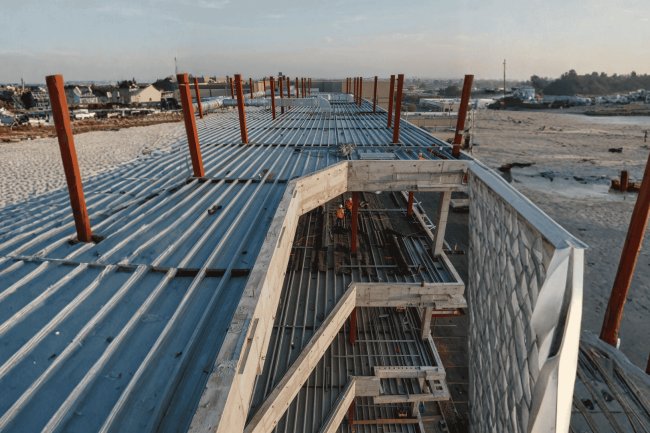
Steel roof deck panels must span perpendicular to supporting members so ribs run parallel to the span direction. In rectangular bays, panels run across joist spacing. Deviations at corners or setbacks require supplemental framing. Layout lines should originate from a control point (column line or centerline) to avoid cumulative misalignment across the roof field.
Side laps must align with joist flanges for fastening. SDI and FM Global specify spacing between 12″–36″ o.c. End laps require minimum 1.5″ bearing per sheet end, influencing joist spacing. Proper sequencing ensures both sheets bear adequately at supports.
A clean plan view can mask discontinuities. Penetration locations must be coordinated with the structural engineer early to preserve diaphragm performance.
Panel orientation and lap detailing are not just placement rules — they drive diaphragm continuity and structural efficiency. Early coordination ensures the roof deck performs as both a gravity system and a lateral load-resisting diaphragm.
Panel Orientation, Span Direction & Diaphragm Continuity
Orienting Panels for Structural Efficiency
Laps, Side Laps & End Laps
Diaphragm Continuity: The Hidden Layout Driver
Key Insight
On low-slope commercial roofs, water management is one of the most critical design responsibilities. Even small drainage errors can trigger ponding water, excessive structural loading, membrane distress, warranty disputes, and accelerated deterioration. Effective drainage planning must account for not only the intended roof slope but also the real-world behavior of the structural system under load, ensuring water consistently reaches drains throughout the building's service life.
Successful roof drainage design considers slope, structural deflection, insulation geometry, drain placement, roofing performance, and future loading conditions as one coordinated system.
The typical minimum roof drainage slope target (2%) for directing water toward drains. However, structural deflection can reduce effective slope after construction, making deflection analysis equally important.
Drainage Planning: Slope, Ponding & Tapered Insulation
Water Must Always Have Somewhere To Go
Roof Drainage Planning Workflow
¼" / FT
Tapered Insulation Influences More Than Drainage
Effective low-slope commercial roof deck layout planning is not a single-discipline task—it is an iterative coordination process that must begin early and involve structural, architectural, and envelope specialists simultaneously. The decisions made during layout planning have direct consequences for structural performance, envelope integrity, constructability, and total project cost.
Confirm the profile, gage, and span capacity against framing grid and superimposed load requirements before any other layout decisions are locked in. FM/UL system compliance must be verified at this stage.
Set panel orientation from a structural column line or building centerline. Propagate the layout in both directions to ensure panel ends bear correctly on supports and side laps land on joist flanges throughout the field.
Coordinate all penetrations, openings, and roof offsets with the structural engineer during layout planning. Establish collector elements and verify that attachment patterns meet SDI diaphragm demand in perimeter and corner zones.
Confirm drain locations, tapered insulation layout, and overflow drain elevations before structural steel is designed. Check long-span bays for ponding stability per SDI procedures. Never leave slope decisions to the roofing subcontractor alone.
Engage structural engineer, roofing consultant, and deck supplier. Select deck type and gage. Verify FM/UL compliance.
Establish layout control line. Propagate panel orientation. Coordinate penetrations and openings with structural engineer.
Verify diaphragm continuity. Establish collector elements. Confirm attachment patterns meet SDI demand in perimeter/corner zones.
Confirm drain locations, tapered insulation layout, overflow elevations. Check ponding stability per SDI. Document slope strategy.
Deck supplier produces shop drawings based on locked-in layout decisions. Field verification before installation.
Minimal cost. Decisions made on paper before any steel is fabricated or deck is ordered. Changes are free.
Expensive. Field modifications, supplemental framing, rework, and schedule delays. Change orders multiply.
Most expensive. Deck removal, structural reinforcement, warranty disputes, and potential liability exposure.
Profile, gage, span capacity, FM/UL compliance verified first.
Panel orientation from column line, propagated bidirectionally.
Penetrations coordinated, collector elements, SDI demand met.
Drain locations, tapered insulation, ponding stability before steel design.
Engage your structural engineer, roofing consultant, and deck supplier at the concept phase to lock in decisions that serve every discipline downstream.
Effective low-slope commercial roof deck layout planning is not a single-discipline task—it is an iterative coordination process that must begin early and involve structural, architectural, and envelope specialists simultaneously. Start with deck type and gage: confirm profile, gage, and span capacity against framing grid and superimposed load requirements before any other layout decisions are locked in, with FM/UL system compliance verified at this stage. Establish a layout control line: set panel orientation from a structural column line or building centerline, propagate bidirectionally to ensure panel ends bear correctly and side laps land on joist flanges. Protect diaphragm continuity: coordinate all penetrations, openings, and roof offsets with the structural engineer during layout planning, establish collector elements, and verify attachment patterns meet SDI diaphragm demand in perimeter and corner zones. Resolve slope and drainage early: confirm drain locations, tapered insulation layout, and overflow drain elevations before structural steel is designed, check long-span bays for ponding stability per SDI procedures, and never leave slope decisions to the roofing subcontractor alone. Roof deck layout planning is most effective—and least expensive—when treated as a pre-design coordination milestone, not a shop drawing exercise. Engage your structural engineer, roofing consultant, and deck supplier at the concept phase to lock in decisions that serve every discipline downstream.
Key Takeaways: Building a Coordinated Roof Deck Layout
Start with Deck Type and Gage
• Profile selected (Type B, Type N, or cellular)
• Gage confirmed (22, 20, or 18)
• Span capacity matches framing grid
• Superimposed loads calculated
• FM/UL system compliance verified
• Insulation attachment method confirmedEstablish a Layout Control Line
• Reference structural column line or centerline
• Propagate layout bidirectionally
• Verify panel ends bear on supports
• Confirm side laps land on joist flanges
• Check field conditions throughout
• Document on structural framing planProtect Diaphragm Continuity
• All penetrations coordinated early
• Openings flagged for EOR review
• Roof offsets documented
• Collector elements established
• Attachment patterns verified
• SDI diaphragm demand met in perimeter/corner zonesResolve Slope and Drainage Early
• Drain locations confirmed
• Tapered insulation layout designed
• Overflow drain elevations set
• Ponding stability checked (SDI)
• Long-span bays verified
• Slope strategy documentedThe Coordination Timeline: When to Engage Each Discipline
Cost Impact of Late Coordination
The Four Pillars of Coordinated Roof Deck Layout
Pre-Design Coordination Milestone, Not a Shop Drawing Exercise
The Coordination Principle
What's Your Reaction?