Steel Deck Coordination for Lightweight Concrete Slabs
Coordinating steel decking with lightweight concrete (LWC) topping slabs demands a level of precision that goes well beyond standard composite floor design. The interplay between deck profile geometry, concrete unit weight, camber behavior, and structural load paths creates a highly interdependent system — one where a single miscommunication between disciplines can cascade into costly field corrections or, worse, structural inadequacy. This guide is written for structural engineers, steel decking detailers, and BIM coordinators who need advanced, actionable coordination guidance — not a primer on deck types. We dive directly into the nuances of LWC slab systems, drawing on real coordination challenges and best practices that are often absent from manufacturer literature. For a broader foundation on deck detailing workflows, visit the Consac Decks Blog or explore comprehensive Joist & Deck coordination resources.
LWC carries a lower modulus of elasticity (approximately 20–30% less than NWC), which directly affects composite stiffness, deflection under live load, and long-term creep behavior. Deck selection must account for the reduced stiffness of the slab composite — engineers must verify that shear connector spacing and weld pattern assumptions in the original design are compatible with LWC's reduced elastic modulus. Span tables for composite decks are calibrated to NWC unless explicitly noted. Using LWC without re-verifying these tables against the actual unit weight is a coordination failure that frequently escapes initial review.
Lightweight aggregate tends to produce a wetter, more workable mix during placement, which increases the risk of bleed water accumulation atop the deck flutes. This affects the bond between the slab and deck, particularly in non-composite applications. Detailers must flag pour-stop and closure plate heights to account for LWC's slightly different flow characteristics. Deck end laps, side laps, and puddle weld spacing all require re-evaluation when LWC is specified post-design — a surprisingly common scenario when the structural engineer of record amends the specification during design development.
Unit Weight Confirmation
Always confirm the exact design unit weight with the structural EOR before finalizing deck section selection and span table lookups. LWC unit weights vary by mix design and aggregate type — 100 pcf and 110 pcf behave very differently in composite calculations.
Camber Reconciliation
LWC reduces the superimposed dead load, which can shift the optimal camber values on joists and beams. Coordinate with joist fabricators early — camber set during fabrication cannot be easily revised in the field. See the Steel Joist Detailing blog for camber coordination best practices.
Fire Rating Verification
UL fire ratings for composite deck assemblies are often unit-weight-specific. Substituting LWC for NWC without re-checking the UL design number can invalidate the fire rating classification. Always pull the current UL Fire Resistance Directory entry and confirm the concrete unit weight matches the design specification.
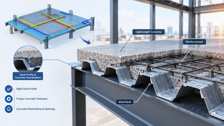
Selecting the correct deck profile for a lightweight concrete slab is not a one-dimensional decision. The structural depth, rib geometry, and concrete cover above the top flute all interact with LWC's material properties to determine composite efficiency, crack control reinforcement requirements, and constructability on the floor.
LWC mixes using expanded shale or expanded clay aggregates typically range from 3/8-inch to 3/4-inch maximum aggregate size. Narrow-rib deck profiles (flute widths under 5 inches) can restrict aggregate flow and create voids within the rib, undermining the composite cross-section. Detailers should flag rib widths below 4.5 inches for LWC applications and coordinate with the concrete subcontractor to confirm mix design compatibility before decks are ordered.
Deck orientation relative to joist framing affects both structural performance and concrete placement logistics. For LWC pours, the lower unit weight reduces formwork pressure but increases the risk of over-pour in wide-flute decks. Coordinate the pour sequence drawing with the deck layout plan to ensure shoring requirements, if any, are flagged early. Pour stops and edge conditions must be detailed to prevent LWC bleed-through at deck perimeters. Review joist and deck coordination protocols for integrated pour sequence documentation.
Always cross-reference the deck manufacturer's composite design tables against the actual LWC unit weight specified — tables default to NWC unless the LWC column is explicitly selected. A mismatch here is one of the most common and costliest coordination errors in LWC slab systems.
Deck Profile Selection & Slab Thickness Coordination
Rib Width & Aggregate Compatibility
Deck Orientation & Pour Sequence
Effective BIM coordination for lightweight concrete slab systems goes far beyond clash detection. The integration of deck geometry, structural framing, embeds, edge conditions, and concrete slab parameters into a federated model requires disciplined data standards and intentional model management practices. The following workflow pillars represent current best practice for LWC deck coordination in multi-discipline BIM environments.
BIM Coordination Workflows
for LWC Deck Systems
Successful steel deck coordination for lightweight concrete slabs requires sustained cross-discipline communication, rigorous verification of material parameters, and a BIM workflow that treats LWC as a distinct system — not a simple substitution for normal-weight concrete. The following checklist synthesizes the most critical coordination touchpoints across the design, detailing, and construction phases.
Confirm Unit Weight Early • Re-Verify Span Tables • Coordinate BIM Models with LWC-Specific Data
What's Your Reaction?