A Beginner's Guide to Reading Wood Nailer Detail Drawings
Wood nailer detail drawings are a foundational element in construction documentation—yet they're often misunderstood by those new to the field. Whether you're stepping into a project management role, joining a CAD team, or reviewing structural packages for the first time, understanding how to read these drawings can make a significant difference in how confidently you navigate a construction set.

What Is a Wood Nailer — and Why Does It Matter?
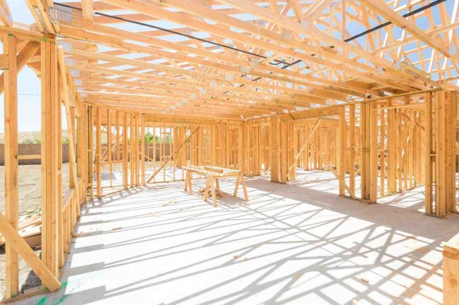
A wood nailer is a piece of dimensional lumber — typically pressure-treated — that is anchored to a structural surface such as a concrete parapet, steel beam, or masonry wall. Its primary function is to provide a nailable substrate for attaching roofing membranes, coping systems, flashing, or other building envelope components that cannot be fastened directly to hard structural materials.
Wood nailers are especially critical at roof edges, parapets, curbs, and mechanical equipment supports. Without a properly installed nailer, roofing systems lose their secure termination point, which can lead to membrane blow-off, water infiltration, and costly repairs.
Wood nailers may appear minor in a drawing set, but their correct installation is directly tied to the long-term weathertightness of the building envelope.
Key Takeaways
- Provides nailable substrate for roofing and flashing
- Critical at roof edges, parapets, curbs, and mechanical supports
- Ensures secure termination point to prevent blow-off and water infiltration
- Directly tied to long-term weathertightness of the building
Key Components Shown in a Wood Nailer Detail
When you open a wood nailer detail drawing, you'll typically encounter several recurring elements. Learning to identify each one — and understanding its role — is the core skill of reading these documents effectively.
The Nailer Itself
Usually depicted as a rectangular cross-section with a wood grain symbol or hatch pattern. Common sizes include 2×6, 2×8, or stacked members. Specifications note treatment type — typically AWPA UC4A or UC4B for ground-contact or rooftop applications.
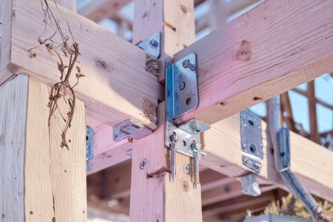
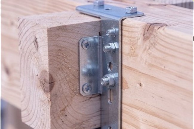
Anchor Bolts and Fasteners
Shown as vertical or angled lines penetrating the nailer and substrate. Detail indicates bolt diameter, embedment depth, spacing, and washer or plate requirements to prevent uplift failure.
Roofing Membrane Termination
Shows how the membrane wraps over or terminates at the nailer. Conditions like clamping bar, counter-flashing, or adhered membrane edge are critical for waterproofing and are always called out with specific materials.
Substrate and Insulation Layers
Depicts the roof deck, rigid insulation, and tapered fill. The nailer must sit flush with or slightly above the finished insulation surface for proper membrane transition.
Understanding the Detail Drawing Format
Drawing Scale
Wood nailer details are typically drawn at 1½"=1'-0" or 3"=1'-0" — large enough to show fastener placement, lumber dimensions, and material layers clearly.
Section Cut Markers
These arrows or bubbles on plan and elevation drawings point you to where the detail is "cut" — giving context for where the nailer sits within the broader assembly.
Callout Bubbles
Each material or component within the detail is tagged with a number or letter that corresponds to a legend or specification note, identifying lumber type, fastener size, and sealant requirements.
Dimension Lines
These indicate the thickness of the nailer, the height above the roof deck, offset from the edge, and other critical measurements that govern the physical installation.
How to Read Dimensions and Tolerances
In wood nailer details, dimensions are not suggestions — they are engineered requirements. A nailer set at the wrong height can compromise drainage slope, create membrane bumps, or interfere with coping installation. Always read dimensions along with general notes, as tolerances (typically ±¼" or ±⅛") may be specified separately from the callouts themselves.
Nailer Height
Vertical dimension from deck to top of nailer, often coordinated with insulation thickness.
Setback Distance
Distance from the roof edge or parapet face, ensuring proper placement and alignment.
Fastener Spacing
Expressed as "@ 24" O.C." (on center), indicating intervals between anchor bolts.
Lumber Width
Horizontal dimension of the nailer member affecting edge distance for membrane or metal edge fastening.
Stacking Configuration
Each layer's thickness and orientation is dimensioned individually when multiple layers are shown.
Common Wood Nailer Conditions You'll Encounter
Parapet Nailer
Installed at the top of a parapet wall to anchor the roofing membrane and coping. Typically bolted to the top of a CMU or concrete wall with the membrane wrapping up and over.
Curb Nailer
Surrounds mechanical curbs such as HVAC units, skylights, or hatches. Raises the membrane above the curb height and provides a nailable surface for counter-flashing and cover strips.
Roof Edge Nailer
Located at the perimeter of a low-slope roof. Acts as the termination point for the roofing membrane and base for a metal drip edge or gravel stop. Critical for wind uplift resistance.
Expansion Joint Nailer
Used at building expansion joints to allow movement while maintaining a weathertight seal. Shows two nailers facing each other with a flexible membrane bellows bridging the gap.
Reading Material Callouts and Specification References
Every component in a wood nailer detail is labeled—and those labels tie directly to the project's specification manual (typically organized under CSI MasterFormat divisions). Understanding this cross-reference system is essential for anyone reading construction documents professionally.
How Callouts Work
A number or letter inside a circle (called a "keynote") appears next to each material in the drawing. A keynote legend on the same sheet—or on a dedicated legend sheet—decodes each tag. For example, keynote "4" might reference:
“Pressure-treated Douglas Fir, 2×6, AWPA UC4A, anchored per structural engineer's requirements.”
When reviewing a nailer detail, always open the keynote legend side-by-side with the drawing. This prevents misidentifying a component and ensures you're specifying or purchasing the correct material.
Specification Divisions to Know
- Division 06 10 00 — Rough Carpentry: Covers lumber type, treatment, and installation.
- Division 07 50 00 — Membrane Roofing: How the membrane interfaces with the nailer.
- Division 07 60 00 — Flashing and Sheet Metal: Metal edge conditions at nailers.
- Division 05 50 00 — Metal Fabrications: Anchor bolts and embedded plates.
Firms like Consac deliver fully coordinated detail packages where drawing callouts and specification sections are precisely aligned—reducing field confusion and RFI volume.
Interpreting Hatch Patterns and Symbols
Detail drawings use standardized hatch patterns to represent different materials without labeling every square inch. Recognizing these patterns speeds up drawing comprehension significantly. Here are the most common ones you'll see in wood nailer details:
Wood Grain Hatch
Diagonal lines with a slight curve — represents the nailer lumber itself. Shown in cross-section and plan view.
Insulation Hatch
Zigzag or wavy lines — represents rigid or batt insulation layers below or around the nailer assembly.
Concrete Hatch
Random dot or triangle pattern — represents cast-in-place concrete or precast elements like the parapet or deck substrate.
Metal / Steel Hatch
Thin diagonal parallel lines at 45° — represents steel deck, embedded angles, or metal edge components adjacent to the nailer.
Common Errors Beginners Make When Reading Nailer Details
Ignoring the Scale Bar
Assuming all details are at the same scale is a costly mistake. Always check the scale notation on each detail, as a sheet may contain multiple scales (e.g., 1½"=1'-0" and 3"=1'-0"). Scaling without confirmation leads to incorrect field measurements.
Confusing Plan View with Section View
A plan view cuts horizontally and shows the nailer from above. A section view cuts vertically to show layering and height. Mixing these up can cause misinterpretation of orientation and installation sequence.
Skipping the General Notes
General notes often contain critical qualifiers — such as "all lumber to be treated per Section 06 10 00" or "anchor bolts per structural engineer." Read these alongside the detail to avoid misinterpretation.
Overlooking Revision Clouds
Revision clouds highlight modifications since the original issue. Always check these clouds and the revision block to ensure you're working from the latest drawings.
How BIM and CAD Have Transformed Nailer Detailing
Traditionally, wood nailer details were hand-drafted or produced in 2D CAD. Today, BIM-integrated workflows have raised the bar—and raised the value—of these construction documents significantly.
3D Model Coordination
In a BIM environment, the nailer is modeled as a 3D object within the full building model. This allows designers to visually confirm that the nailer height clears insulation layers, doesn't conflict with mechanical curbs, and aligns with coping system geometry—all before a single sheet is printed.
Automated Detail Generation & Clash Detection
Automated clash detection in BIM tools like Revit or Navisworks flags conflicts between nailers and adjacent MEP or structural elements. This proactive coordination reduces RFIs and field changes—particularly at complex roof conditions with multiple curbs and penetrations in close proximity.
Centralized Data Management
Sections and details can be extracted directly from the 3D model, ensuring that what is shown in the detail drawing accurately reflects the modeled assembly. This eliminates discrepancies between design intent models and 2D construction documents that often plague traditional workflows.
BIM models carry embedded data—lumber species, treatment level, fastener specifications, and supplier information—that can be extracted for procurement, QA/QC, and as-built documentation. This data continuity from design through construction is one of BIM's most practical advantages for nailer-intensive projects.
Key Takeaways for Your Next Project
Reading wood nailer detail drawings is a skill that builds with practice and intentional study. As you encounter more projects, patterns become familiar — improving your ability to catch errors, ask the right questions, and communicate clearly with field teams.
-
01. Always Check the Scale
Confirm the drawing scale before taking any measurements or making installation decisions based on graphic dimensions.
-
02. Cross-Reference Callouts with Specs
Every keynote in the detail links to a specification section. Never assume material selection — always verify through the project's specification manual.
-
03. Coordinate Across Disciplines
Nailer details intersect with structural, roofing, and MEP drawings. Review them together to identify conflicts before they reach the field.
-
04. Understand the Condition Type
Identify whether you're looking at a parapet, edge, curb, or expansion joint nailer — each has distinct geometry, fastener logic, and membrane termination requirements.
-
05. Leverage Digital Tools
BIM and CAD platforms improve accuracy and coordination. Use your BIM model to verify detail geometry before finalizing drawing packages.
Build Confidence in Construction Documentation
Wood nailer detail drawings may seem like a small piece of a large project puzzle — but their accuracy and proper interpretation directly impacts roofing system performance, waterproofing longevity, and overall construction quality. Developing fluency with these documents is a genuinely valuable professional skill.
Whether you're a project manager reviewing submittals, a field superintendent coordinating installation, or a CAD technician producing the drawings, the ability to read, interpret, and act on wood nailer details with confidence will serve you across every building type and project scale.
Ready to Elevate Your Documentation?
- Architectural & structural detailing
- BIM modeling & coordination
- CAD drafting & as-built documentation
- Construction document review
Start with one drawing, one detail, and one condition at a time. With consistent practice and the framework laid out in this guide, what once seemed like a dense technical document will become a clear and actionable set of instructions.
What's Your Reaction?