Steel Roof Deck Detailing for Industrial Facilities
A comprehensive technical reference for structural and detailing engineers navigating the complexities of steel roof deck design, connection detailing, and BIM coordination in heavy industrial environments. From diaphragm load paths to edge conditions, this guide delivers actionable best practices grounded in field-proven standards.
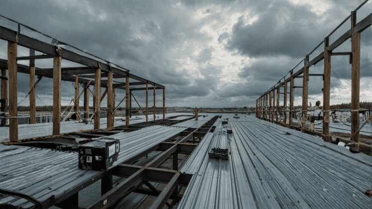
Why Industrial Roof Deck Detailing Demands a Different Approach
Industrial facilities place roof deck systems under conditions that are fundamentally different from conventional commercial buildings. Dynamic loading, vibration, thermal movement, corrosive environments, suspended process systems, and long-span structural layouts create detailing challenges that require project-specific engineering rather than standard commercial solutions.
Industrial Buildings Operate Under Different Structural Realities
Standard Roof Conditions
• Predictable occupancy loads
• Limited vibration exposure
• Minimal thermal extremes
• Relatively few penetrations
• Conventional support layouts
High-Demand Conditions
• Process equipment vibration
• Thermal cycling
• Chemical exposure
• Extensive MEP support systems
• Long-span structural demands
The Roof Deck Is Rarely a “Dead” Element
Industrial roof decks frequently support suspended mechanical, electrical, plumbing, process piping, cable trays, and maintenance systems. The deck remains under continuous operational loading, experiences ongoing thermal movement, and often receives additional penetrations long after initial construction.
Longer Span Requirements
Longer spans often require roof deck profiles of 3 inches or greater to maintain stiffness and control deflection under service loading.
Equipment Reinforcement
Heavy rooftop and process equipment frequently require local reinforcement and enhanced support detailing.
Thermal Movement Control
Large roof areas require deliberate expansion joint strategies and sliding connection details to accommodate movement.
Corrosion Protection
Exposure conditions may require upgraded coatings, stainless materials, aluminum components, or specialty corrosion systems.
Profile depth, base-metal thickness, rib geometry, support spacing, loading, deflection, and diaphragm demand must be selected as one coordinated system.
A common choice for moderate roof spans, with wide ribs that can provide useful bearing for insulation and membrane systems.
A deeper profile provides substantially greater section stiffness and is commonly considered for longer spans between joists or purlins.
Reserved for unusually long spans or concentrated rooftop equipment loads that require greater load distribution and stiffness.
Select the lightest base-metal thickness that satisfies gravity strength, construction-stage performance, deflection, bearing, equipment loads, and lateral-load-path requirements.
Verify allowable load, construction-stage deflection, roof live-load deflection, wind response, ponding risk, equipment clearance, and any ceiling or finish requirements.
A gauge that passes vertical load may not satisfy the lateral load path.
Select the profile that matches the span and loading environment, then select the base-metal thickness that satisfies strength, serviceability, construction, bearing, and diaphragm requirements together. Verify every choice against the exact approved product table—not a generic profile label.
Deck Profile Selection & Structural Span Criteria
Moderate Spans
Industrial Long Bays
Extreme Conditions
Thickness Follows Span, Load & Diaphragm
Often a practical starting point for industrial roof construction traffic, subject to design verification.
Consider where combined gravity and diaphragm demands require greater capacity.Strength Is Not the Whole Check
Profile Selection Workflow
Gravity and Diaphragm Design Are Coupled
The Selection Principle
Attachment detailing governs both gravity load transfer and diaphragm performance. Every fastener pattern decision affects both demands. Engineers must coordinate fastener layouts with diaphragm analysis rather than treating them as sequential tasks.
Sidelap connections (button punch, screws, welds) are critical for diaphragm performance. Spacing (12", 18", 24" o.c.) must match calculations. Perimeter and corner zones require tighter spacing. Detail sheets must explicitly call out patterns by zone — leaving this to contractor discretion is a costly error.
Attachment detailing is not generic. Deck-to-support welds, sidelap spacing, and perimeter closures must be explicitly coordinated with diaphragm analysis. Generic notes invite RFIs and rework — precise detailing ensures structural reliability in industrial applications.
Critical Attachment and Connection Details
Deck-to-Structural-Support Attachments
Sidelap Fastening
Edge, Perimeter, and Cantilever Conditions
Key Insight
Industrial roof systems experience significant thermal movement and are heavily populated with equipment penetrations. These conditions introduce structural discontinuities and coordination challenges that demand far more rigorous detailing than conventional roof assemblies. Successful projects address expansion joints, penetrations, framing reinforcement, and documentation requirements as integrated parts of a comprehensive roof strategy.
Provide a structural deck gap, typically 1 to 2 inches wide, bridged with a compliant prefabricated expansion joint cover assembly.
Each side of the joint must bear on separate support members. Deck sheets must never span continuously across the expansion gap.
Sliding clips or slotted-hole details permit thermal movement while avoiding restraint-induced stresses.
Collector and diaphragm design must explicitly account for the lateral load discontinuity created by the joint.
Penetrations larger than a deck rib width, typically greater than 3 to 4 inches, require engineered headers, trimmers, or supplemental framing to redirect loads around the opening.
Equipment curbs carrying concentrated loads require deck reinforcement using channels, angles, hat sections, or other engineered support components.
Establish a formal penetration coordination cutoff before deck shop drawing submittal. Post-cutoff changes must follow structured review procedures.
Field-cut penetrations lacking engineered headers are among the most frequently identified deficiencies during industrial roof inspections. Unauthorized openings can compromise structural capacity, diaphragm behavior, fire ratings, and roofing warranty requirements.
Expansion Joints, Penetrations, and Special Conditions
Two Conditions That Drive Industrial Roof Coordination
Expansion Joint Detailing Requirements
Thermal Movement Management Strategy
Framed Openings
Reinforced Curbs
Coordination Cutoff
Unengineered Field-Cut Penetrations
A disciplined BIM and quality-control workflow resolves conflicts before fabrication, makes shop drawings reviewable, and creates a reliable record for future facility maintenance.
Represent panel lengths, run direction, bearing, sidelap orientation, and attachment zones. Coordinate deck direction with joist top chords and the engineer’s diaphragm zone map.
Shop drawings should show orientation arrows, run direction, sidelap patterns, bearing lengths, expansion joints, penetrations, headers, edge angles, welds, and coating requirements.
Verify attachment work in the field, record deficiencies, require correction and re-inspection, and complete the punch list before roofing work hides the deck.
Geometry without metadata is not enough for reliable coordination.
Panel orientation, run arrows, support grid, and sheet identification.
Interior, perimeter, corner, sidelap, collector, and special patterns.
End bearing, expansion joints, gaps, laps, and closure conditions.
Penetrations, headers, edge angles, welds, and curb interfaces.
The Statement of Special Inspections should identify the required scope and frequency for deck attachment work as determined by the governing code, project documents, jurisdiction, and design professional.
Resolve major framing, deck direction, equipment, and penetration conflicts before the design is fixed.
Verify the coordinated model against the issued structural, architectural, and MEP documents.
Close unresolved clashes and hold a multi-trade coordination meeting before approval to fabricate.
Model the deck with meaningful information, issue drawings that answer installation questions, inspect attachment work to the governing requirements, and close every clash before fabrication. BIM is valuable only when its information reaches the field and remains trustworthy afterward.
BIM Coordination, Shop Drawings & Quality Control
Model the Actual Deck
Make Drawings Installable
Close the Quality Loop
Carry the Data with the Panel
Minimum Shop Drawing Content
Write the Inspection Plan into the Project
Clash Detection Milestones
The Quality Principle
What's Your Reaction?