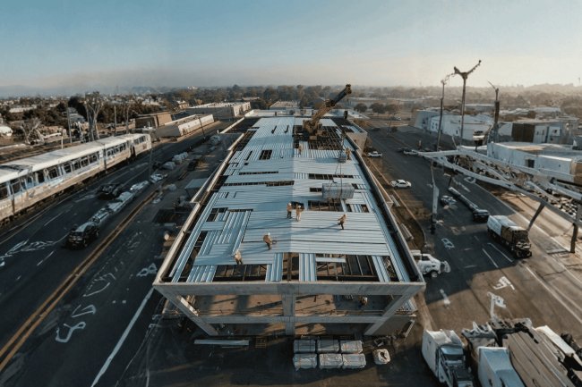
Floor Deck Detailing for Multi- Story Steel Frames
Precision in floor deck detailing is the invisible backbone of every successful multistory steel project. From composite action verification to edge angle spec, the decisions made at the detailing stage ripple through fabrication, erection, and long term structural performance. This guide addresses the practical, shop-drawing-level decisions that structural engineers and steel detailers encounter daily on multi-story framing projects — covering bearing requirements, side-lap and end-lap fastening, pour-stop configurations, deck-to-beam attachment, and coordination checkpoints that keep field crews productive and inspectors satisfied.

Understanding Deck Orientation & Bearing Requirements
Deck orientation is one of the most important decisions in composite floor deck detailing. The direction of deck ribs relative to supporting framing controls structural capacity, diaphragm behavior, stud placement, bearing performance, and installation efficiency. Equally important are bearing requirements, which ensure deck panels remain stable under construction loads and wet-concrete placement conditions. These issues must be resolved during detailing rather than becoming field-installed fixes.
Orientation Determines Performance
A correctly oriented composite deck achieves efficient load transfer, reliable composite action, and predictable diaphragm performance. A poorly detailed orientation introduces structural inefficiencies, installation conflicts, and avoidable RFIs.
Three Critical Detailing Factors
Deck Orientation
Controls structural efficiency and composite behavior.
Bearing Length
Prevents deck instability and support failures.
Edge Support
Critical at cantilevers and perimeter conditions.
Perpendicular Orientation
Composite deck performs best when deck ribs run perpendicular to the primary supporting beams. This arrangement allows deck sheets to span efficiently between supports, supports proper stud installation within the deck ribs, and aligns composite slab behavior with structural design assumptions.
Benefits Of Perpendicular Deck Layout
When Ribs Run Parallel To Framing
Certain cantilevers, irregular floor geometries, and non-orthogonal framing arrangements may force deck ribs to run parallel to supporting members. This condition should never be treated as routine and must be clearly identified on the layout drawings.
Minimum Bearing Requirements
Consequences Of Inadequate Bearing
Cantilever & Spandrel Beam Conditions
Deck overhangs and slab cantilevers require continuous edge support. The slab edge force cannot be carried solely by unsupported deck sheets. Structural edge members must be detailed to support both construction and permanent loads.
Typical Solutions
- Structural edge angles
- Pour-stop channels
- Perimeter support members
Common Consequence
Missing edge-angle details are one of the most common causes of RFIs and installation delays during deck erection.
Layout Plan Coordination Checklist
Bearing And Orientation Are Non‑Negotiable
Composite floor deck systems perform best when ribs run perpendicular to supporting framing and prescribed bearing lengths are maintained at every support condition. Parallel-rib zones, irregular framing, and cantilever edges require enhanced detailing and explicit notation on layout drawings. By resolving orientation, support, and bearing requirements during detailing, engineers eliminate many of the most common causes of installation delays, RFIs, and construction-stage failures.
The fastening schedule directly affects deck attachment, diaphragm capacity, and field installation. Each connection type should be clearly identified on the applicable deck detail and coordinated with the structural design.
Puddle welds provide the primary attachment between the deck and supporting structural members. The weld spacing should follow the diaphragm design and be coordinated with the structural engineer's zone map.
Side-lap connections tie adjacent sheets together along their longitudinal edges and contribute directly to diaphragm shear resistance. The selected connection type and spacing should reflect the demand in each diaphragm zone.
Confirm support attachments, side-lap fasteners, end-lap conditions, weld requirements, diaphragm zones, and manufacturer criteria before issuing the deck detail sheets.
Fastening patterns should never be selected independently of the diaphragm design. Coordinate the deck drawings with the structural engineer's connection schedule, applicable SDI guidance, approved manufacturer information, and the actual project conditions.
Fastening Patterns: Side-Lap, End-Lap & Puddle Welds
Puddle Welds
Side-Lap Fasteners
Verify Every Connection
Match the Structural Schedule
Pour-stops and edge angles are among the most frequently overlooked details in composite deck construction, yet they are critical to successful concrete placement. These components define slab boundaries, support perimeter loads, prevent concrete blowout, and establish the final edge geometry of the floor system. A complete deck package must clearly identify pour-stop dimensions, material thickness, support requirements, attachment methods, and coordination with structural framing.
Field crews rely on pour-stop and edge-angle details before concrete placement begins. Missing or incomplete edge details are among the most common sources of RFIs, schedule delays, and field modifications.
Perimeter slab edges supported by spandrel beams commonly use structural steel angles welded or bolted to the beam's top flange. These members contain concrete, provide edge support, and maintain slab geometry during placement and service.
Discontinuous edge-angle installation creates weak points that can result in concrete blowout during placement. Edge support members should extend continuously along the slab perimeter unless specifically engineered otherwise.
Deck openings create free slab edges that require dedicated edge support and closure detailing. Openings larger than one square foot typically require supplemental framing beneath the deck perimeter.
Deck termination at columns often requires special fabrication. Deck ribs usually cannot bear directly against column flanges or webs without dedicated support details. Closure plates, bent deck segments, or seat angles are commonly required.
Commonly used where unsupported spans are less than 6 feet and construction loading remains within normal ranges.
Recommended for longer cantilevers, larger unsupported edge conditions, or construction loads exceeding 50 psf.
Pour-stops and edge angles may represent a small percentage of the total deck package, but they govern the constructability of the entire slab system. Properly detailed edge conditions prevent concrete loss, support perimeter loads, coordinate with façade systems, ensure opening stability, and eliminate many of the RFIs that commonly delay steel deck installation. Successful projects treat edge detailing as a primary design responsibility rather than a fabrication afterthought.
Pour-Stop & Edge Angle Detailing
Concrete Cannot Be Placed Without Proper Edge Detailing
Every Deck Package Must Define
Spandrel Beam Edge
Continuous Support Is Required
Interior Slab Edges & Openings
Opening Detail Requirements
Column Conditions
Pour-Stop Gauge Guidelines
Standard Condition
Heavy Duty Condition
Always Coordinate Final Height
Detailing Checklist
Edge Details Must Be Fully Defined Before Concrete Placement
Every floor-deck penetration requires coordination between structural framing, deck geometry, reinforcement, and edge conditions. Proper opening detailing prevents omissions that can create fabrication problems, field conflicts, and costly rework.
Irregular openings at columns, shafts, re-entrant corners, and other non-standard conditions often require infill deck sections or formed closure plates. These pieces should be fully dimensioned and included with the main deck package rather than relying on field cutting.
Openings can create concentrated stresses and cracking demands that require supplemental reinforcing. The structural engineer's slab reinforcement plan should be reflected in the deck detail, especially around re-entrant corners and other high-stress locations.
Every opening should be resolved before the deck package reaches fabrication. The final detail should clearly communicate the opening geometry, supplemental framing, infill or closure requirements, reinforcement, connections, and coordination with the deck span direction.
Deck Openings, Infill & Trimmer Framing
Infill & Closure Plates
Slab Reinforcement at Openings
Floor deck detailing is one of the most coordination-intensive activities within a multi-story steel building project. Structural framing, composite slab design, architectural requirements, MEP penetrations, fire-resistance assemblies, and construction sequencing all converge within a single deck package. The following checklist represents the minimum verification process that should occur before a deck detailing package is released for fabrication and construction.
Successful deck packages are not created by drafting alone. They emerge from coordinated review between structural engineers, deck suppliers, steel fabricators, architects, MEP designers, and field construction teams.
Verify deck gauge (18 ga., 16 ga., or 20 ga.) and deck profile depth (1.5 in., 2 in., or 3 in.) match the Engineer of Record's structural design assumptions. Any substitution impacts composite behavior, construction-stage deflection, diaphragm capacity, and fire-rating performance. Changes require formal approval and updated calculations.
Confirm minimum required bearing is achievable throughout the project. Narrow beam flanges, coped beam ends, and connection zones frequently create insufficient bearing conditions that may not become visible until fabrication or installation.
Deck fastening patterns should follow the structural diaphragm design zones. Weld spacing, side-lap fastening patterns, and diaphragm detailing frequently vary across the floor plate. Applying a uniform fastening schedule everywhere may result in non-compliance with diaphragm design requirements.
Review stud placement against deck rib geometry. Studs should be centered within deck ribs whenever possible while maintaining required edge clearances and cover. Deck seams, narrow ribs, and framing congestion must be identified before fabrication begins.
Confirm pour-stop elevations match total slab thickness at every perimeter condition, opening edge, and structural transition. Inspect continuity at columns, beam intersections, and stair openings. Even a small discontinuity can create significant concrete leakage during placement.
Cross-check all deck openings against the most current architectural and MEP drawings. Include stairs, elevators, shafts, future penetrations, electrical rooms, plumbing risers, and mechanical openings. Missing openings frequently lead to costly field-cutting operations after deck installation.
Every deck package should reference the applicable UL floor-ceiling assembly designation. Building inspectors and code officials commonly verify these assemblies during inspections. Missing fire-rating references can create occupancy approval delays late in the project schedule.
Deck shop drawings must be tied directly to the structural revision used during detailing. Fabricating deck packages from superseded structural sets remains one of the most expensive and preventable coordination failures on steel-frame projects.
The most valuable deck detailers are not simply producing drawings. They are identifying conflicts before fabrication, exposing inconsistencies between disciplines, validating structural assumptions, and reducing field uncertainty. Their work prevents change orders, minimizes RFIs, protects schedule performance, and improves constructability across the entire building project.
Floor deck detailing is not a single-discipline drafting exercise. It is a multi-disciplinary coordination process that connects structural design, steel fabrication, architectural requirements, MEP systems, fire-rating compliance, and construction sequencing. The detailer's responsibility is to identify and resolve conflicts before steel is fabricated and before concrete is placed. A complete, coordinated deck package is one of the highest-value deliverables on any multi-story steel construction project because it directly impacts cost, schedule, quality, and field productivity.
Detailing Coordination Checklist & Common Pitfalls
Most Deck Problems Are Coordination Problems
Required Coordination Participants
01. Confirm Deck Gauge & Profile
02. Verify Beam Flange Width & Deck Bearing
03. Overlay The Diaphragm Zone Map
04. Coordinate With Shear Stud Layout
05. Verify Pour-Stop Height & Continuity
06. Review Openings Against Architectural Plans
07. Include Fire-Rating Designations
08. Track Structural Revisions
Common Deck Detailing Pitfalls
Recommended Verification Workflow
What Great Detailers Actually Do
Floor Deck Detailing Is A Coordination Discipline
What's Your Reaction?