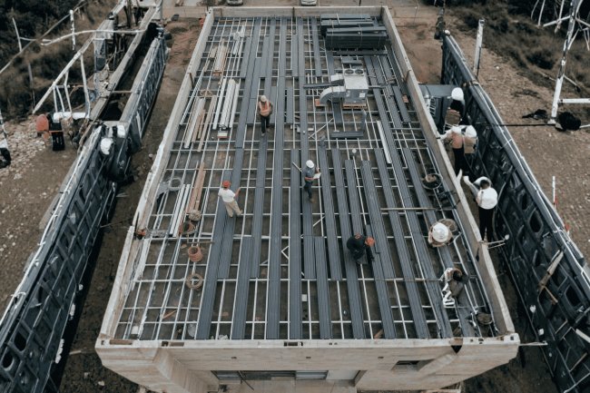
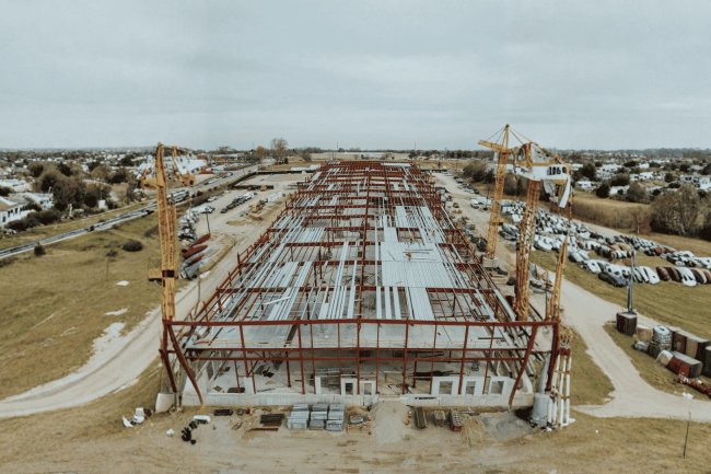
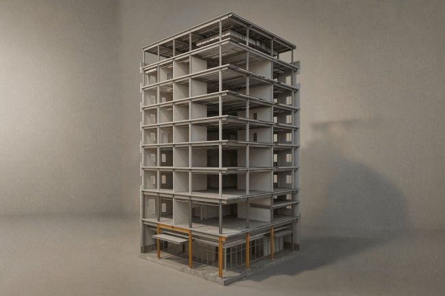
Roof Deck Support at Step-Down Roof Areas
A focused technical reference for structural engineers and detailers navigating one of the most detail-intensive conditions in metal roof deck design — the step-down transition. Where roof elevations change, load paths shift, diaphragm continuity is interrupted, and framing geometry becomes complex. This presentation addresses the structural principles, detailing strategies, and common field pitfalls that define best practice at step-down conditions.
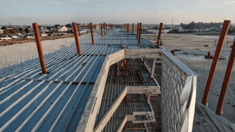
What Is a Step-Down Roof Area?
A step-down roof area occurs when adjacent roof surfaces exist at different elevations, creating a vertical offset within the building's roof structure. While architecturally common, these transitions are among the most detail-sensitive areas in roof deck design because they simultaneously affect gravity load transfer, diaphragm continuity, wind uplift resistance, drainage behavior, and framing coordination. Successful detailing requires treating the step as a structural transition zone rather than simply a change in roof elevation.
One Elevation Change. Multiple Structural Challenges.
At a roof step, deck support conditions, diaphragm load paths, drainage behavior, and wind uplift demands all change simultaneously. This concentration of variables is what makes step-down roof areas so important to resolve early in design.
The Basic Step-Down Roof Concept
Three Structural Challenges Created by Every Step
Vertical Load Transfer
Deck ends, joints, and transitions must safely transfer gravity loads into supporting framing without relying on unsupported deck projections.
Diaphragm Discontinuity
Upper and lower roof diaphragms often require collectors, chords, or transfer elements to maintain lateral load paths.
Anchorage Requirements
Deck edges at the step require positive connection to resist uplift, seismic forces, sliding, and rotation.
One Structural Member Often Supports Two Roofs
Spandrel beams, structural walls, and ledger conditions frequently act as the support for both the upper roof edge and the lower roof edge simultaneously. This dual-support role concentrates detailing requirements into a very narrow zone.
The structural member at the step—whether a spandrel beam, a CMU bearing wall with a steel ledger, or a moment frame column-to-beam connection—must be sized and detailed to handle combined loading from both roof levels simultaneously. Engineers frequently underestimate the cumulative tributary area at this condition, especially when the step beam also supports mechanical equipment or rooftop units positioned near the transition.
The upper deck panel terminates at the step. Depending on the structural system, the panel may bear directly on the top flange of the step beam or on a closure plate/angle welded to the beam web.
The lower deck panel begins at the same step beam, bearing on the lower flange or on a beam-mounted angle. This edge is often more vulnerable because the lower roof is the "receiving" side—it must carry not only its own gravity loads but also any drainage surcharge from the upper level during storm events.
The step beam must be sized to handle combined loading from both roof levels simultaneously. Carry-down loads from upper and lower roofs, plus any parapet or coping dead load, must be explicitly accounted for in beam design and connection design.
Engineers frequently underestimate the cumulative tributary area at this condition. The step beam collects load from both roof planes, effectively doubling the tributary width compared to a single-level beam.
When the step beam also supports mechanical equipment or rooftop units positioned near the transition, concentrated loads must be added to the combined tributary load. This is a common underestimation.
Beam-to-column or beam-to-wall connections must be designed for the combined load from both roof levels. Do not design connections for single-level loads only.
Engineers frequently underestimate cumulative tributary area. Step beam collects load from both roof planes—effectively doubling tributary width.
RTUs or equipment near step transition add concentrated loads. Commonly overlooked in beam design.
Lower roof receives upper roof drainage. Storm surcharge must be included in load calculations.
Sidelap and end-lap fastening within last rib critical to prevent edge lift, especially in high-wind zones.
First row of fasteners on lower roof sees highest net uplift. Verify capacity against wind loads.
Flashing and membrane termination must be integrated with structural step, not fighting it.
Upper roof tributary + lower roof tributary + parapet/coping dead load + mechanical equipment (if present). Apply load combinations per ASCE 7.
Uplift on both roof levels, highest at lower roof first fastener row. Corner and perimeter zones per ASCE 7. Verify connection capacity.
Lower roof must carry drainage from upper level during storm events. Include ponding load per SDI procedures in long-span bays.
In seismic zones, positive attachment via puddle welds or power-actuated fasteners critical. Diaphragm forces transfer through step beam.
Carry-down loads from both roof levels, plus any parapet or coping dead load, must be explicitly accounted for in beam and connection design.
The structural member at the step—whether a spandrel beam, CMU bearing wall with steel ledger, or moment frame column-to-beam connection—must be sized and detailed to handle combined loading from both roof levels simultaneously. The step beam must be treated as a dual-tributary member in all gravity load calculations: carry-down loads from both roof levels, plus any parapet or coping dead load, must be explicitly accounted for in beam design and connection design. Engineers frequently underestimate the cumulative tributary area at this condition, especially when the step beam also supports mechanical equipment or rooftop units positioned near the transition. The upper deck edge condition requires minimum 1½ inch bearing per SDI, sidelap and end-lap fastening within the last rib to prevent edge lift, closure angle or pour stop if concrete topping exists, and positive attachment via puddle welds or power-actuated fasteners—especially critical in high-wind or seismic zones. The lower deck edge condition is often more vulnerable: the lower roof is the "receiving" side, carrying its own gravity loads plus any drainage surcharge from the upper level during storm events. Details include scupper or overflow drain coordination at step fascia, deck panel starter rib orientation for water management, verified uplift capacity of the first row of fasteners (which see highest net uplift from wind), and flashing and membrane termination integrated with the structural step. Never fight the structure with the roofing—integrate them from the start.
Framing the Step: Support Conditions and Load Path
Upper Deck Edge Condition
• Minimum 1½ inch bearing per SDI recommendations
• Sidelap and end-lap fastening within last rib to prevent edge lift
• Closure angle or pour stop if upper roof has concrete topping
• Positive attachment via puddle welds or power-actuated fasteners
• Especially critical in high-wind or seismic zonesLower Deck Edge Condition
• Scupper or overflow drain coordination at step fascia
• Deck panel starter rib orientation (proper nest vs. male-end-up)
• Uplift capacity of first row of fasteners (highest net uplift)
• Flashing and membrane termination integrated with structural stepLoad Path: Dual-Tributary Beam Design
Combined Loading
Tributary Area
Mechanical Loads
Connection Design
Step Beam Support Conditions
Support Type
Description
Load Capacity
Detailing Complexity
Spandrel Beam
Steel beam spanning between columns or walls
High moment and shear capacity
Moderate
CMU Bearing Wall + Ledger
Concrete masonry wall with steel ledger angle
High compression, limited moment
High
Moment Frame Connection
Column-to-beam rigid connection
Highest moment and lateral capacity
Highest
Critical Coordination Points at Step Conditions
Step Beam Load Calculation Framework
Gravity Loads
Wind Loads
Drainage Surcharge
Seismic Loads
The Step Beam Must Be Treated as a Dual-Tributary Member
The Step Framing Principle
At step-down roof conditions, diaphragm continuity is often overlooked. Because upper and lower decks sit at different elevations, shear cannot transfer directly through the deck field. A deliberate load path must be established through the supporting framing system.
Step transitions interrupt diaphragm continuity unless collectors, drag struts, and cross-step shear paths are explicitly designed. Proper detailing ensures lateral loads are transferred safely across elevation changes without hidden discontinuities.
Diaphragm Continuity at the Step Transition
Collector and Drag Strut Requirements
Cross-Step Shear Transfer
Key Insight
Step-down roof transitions concentrate structural, roofing, and enclosure challenges into a small area of the building. While the framing concept may appear simple on drawings, many field failures originate from overlooked detailing decisions involving bearing length, closure systems, span orientation, thermal movement, and uplift resistance. A carefully coordinated detail prevents construction improvisation and protects long-term performance.
The most successful step-down details explicitly define bearing, attachment, closure conditions, movement accommodation, and roofing transitions before steel fabrication and deck installation begin.
Minor framing deviations can transform a compliant detail into a partially unsupported deck edge, creating structural, roofing, and uplift-performance concerns.
When closure plates, insulation transitions, flashing supports, and deck edge supports are left to field interpretation, water infiltration, air leakage, thermal bridging, and premature roofing failures frequently follow.
Detailing Best Practices & Common Field Errors
Every Step Edge Is A High-Risk Structural & Envelope Zone
Four Essential Detailing Practices
Actual Bearing Reduced to Near Zero
Missing Closure Details Create Predictable Failures
What Happens When Movement Is Restrained
Step-down roof conditions concentrate structural, waterproofing, and envelope demands into a single narrow zone of the building. Disciplined detailing—coordinated between the structural engineer, the deck designer, and the roofing consultant—is the only reliable path to a durable, code-compliant transition. Use the checklist below as a QA gate before finalizing construction documents.
Trace every load—gravity, uplift, lateral—through the step condition before finalizing any detail. If you cannot draw the load path, the detail is not complete.
Step-down conditions require explicit, dimensioned details on the structural drawings. Field improvisation at these locations routinely produces both structural deficiencies and envelope failures.
Engage the roofing consultant and MEP team during schematic design when step locations are first established—not at construction document completion.
Step beam sized for single roof level only, not combined tributary from both levels. Results in overstressed beam and potential deflection issues.
Deck bearing length less than 1½ inches at step edge. Leads to deck pull-out, edge lift, and potential collapse in high-wind events.
Scupper or overflow drain not coordinated with step framing. Water backs up, infiltrates, and causes envelope failure.
Cross-step shear transfer mechanism not identified or detailed. Diaphragm forces cannot flow, compromising lateral stability.
Insulation blocking and thermal bridging mitigation not shown at step face. Condensation, energy loss, and comfort issues result.
Roofing consultant and MEP engaged at CD completion, not schematic design. Conflicts discovered in field, requiring expensive changes.
Upper roof → upper deck → step beam → columns/walls → foundation. Lower roof → lower deck → step beam (same member) → columns/walls → foundation. Combined tributary must be used in beam design.
Wind uplift → deck fasteners (edge rows critical) → step beam → beam end connections → columns/walls → foundation. Verify fastener capacity against ASCE 7 corner/perimeter zones.
Diaphragm shear → deck → collector/drag strut parallel to step → cross-step shear transfer mechanism → step beam → lateral system. All components must be identified and detailed.
Establish step locations. Engage roofing consultant and MEP team. Confirm step beam concept and load path strategy.
Size step beam for combined tributary. Detail collector/drag strut. Coordinate scupper/overflow drain locations with framing.
Confirm deck bearing length ≥1½". Verify edge fastener uplift/shear against ASCE 7. Show closure angle/pour stop at upper edge.
Review scope explicitly includes step-down conditions. Verify deck span direction, starter rib orientation, flashing coordination, insulation blocking.
Step-down conditions require explicit, dimensioned details on the structural drawings. Disciplined detailing coordinated between structural engineer, deck designer, and roofing consultant is the only reliable path to a durable, code-compliant transition.
Step-down roof conditions concentrate structural, waterproofing, and envelope demands into a single narrow zone of the building. Disciplined detailing—coordinated between the structural engineer, the deck designer, and the roofing consultant—is the only reliable path to a durable, code-compliant transition. Use the structural design checklist and detailing coordination checklist as QA gates before finalizing construction documents. The three guiding principles drive every decision: Load Path First—trace every load (gravity, uplift, lateral) through the step condition before finalizing any detail; if you cannot draw the load path, the detail is not complete. Detail, Don't Assume—step-down conditions require explicit, dimensioned details on structural drawings; field improvisation at these locations routinely produces both structural deficiencies and envelope failures. Coordinate Early—engage the roofing consultant and MEP team during schematic design when step locations are first established, not at construction document completion. Step beam must be sized for combined tributary gravity from both roof levels, collector/drag strut forces calculated for lateral loads parallel to step, cross-step shear transfer mechanism identified and detailed, deck bearing length ≥1½ inch confirmed, uplift and shear demand at edge fasteners verified against ASCE 7 zone, expansion/movement accommodation detailed at long steps, and step beam end connections designed for axial + bending interaction. Deck span direction confirmed and consistent with design assumptions, closure angle or pour stop shown at upper deck edge, lower deck starter rib orientation and drainage slope confirmed, flashing and membrane termination coordinated with structural step height, insulation blocking and thermal bridging mitigation shown at step face, scupper/overflow drain location coordinated with step framing layout, and shop drawing review scope includes step-down conditions explicitly.
Key Takeaways and Detailing Checklist
Structural Design Checklist
Detailing and Coordination Checklist
Three Guiding Principles for Step-Down Conditions
Common Failure Modes at Step-Down Conditions
Underestimated Tributary
Insufficient Bearing
Uncoordinated Drainage
Missing Shear Transfer
Thermal Bridging
Late Coordination
Step-Down Condition: Load Path Verification
Coordination Timeline: When to Engage Each Discipline
Field Improvisation at Step Locations Routinely Produces Structural Deficiencies and Envelope Failures
The Step-Down Principle
What's Your Reaction?