Roof Deck Detailing for Loading Dock Areas
Loading dock zones represent one of the most structurally demanding intersections in commercial and industrial building design. Where the roof structure meets the loading dock interface, engineers and detailers face a convergence of concentrated dynamic loads, aggressive environmental exposure, and complex geometric transitions that demand precision detailing at every level. This presentation addresses the critical design considerations, structural detailing strategies, and coordination requirements specific to roof deck systems at and above loading dock areas — a topic that sits at the crossroads of structural performance, weatherproofing, and constructability.
Why Loading Dock Zones Demand Special Roof Deck Attention
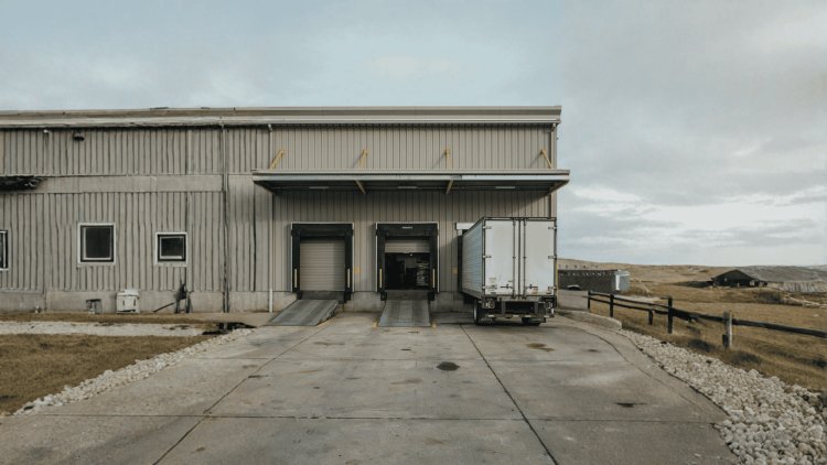
Loading dock areas represent one of the most demanding environments in industrial construction. Unlike standard warehouse roof zones, dock areas combine vehicle impacts, thermal movement, moisture exposure, suspended equipment, and complex perimeter conditions within a concentrated structural region. These overlapping forces make roof deck detailing around loading docks a critical engineering exercise rather than a routine roofing task.
Loading Docks Concentrate Multiple Extreme Load Cases
Dynamic impacts, environmental exposure, suspended systems, and structural movement all converge at the loading dock, making this area one of the most detail-sensitive locations in the entire building envelope.
Predictable Conditions
• Uniform roof loading
• Limited moisture exposure
• Minimal impact vibration
• Consistent temperatures
Extreme Conditions
• Thermal movement cycles
• High humidity variation
• Suspended equipment loads
• Wind-critical edge conditions
Key Structural Challenges
Dynamic Impact
Truck dock impacts propagate vertically into roof framing, deck supports, and connection assemblies.
Thermal Cycling
Interior and exterior temperature differences generate repeated expansion and contraction demands.
Moisture Ingress
Humidity gradients and condensation accelerate corrosion at perimeter and transition zones.
Edge Uplift Resistance
Loading dock canopies and perimeter roof zones experience elevated wind uplift pressures requiring enhanced attachment schedules and boundary reinforcement.
Flashing Integration
Perimeter deck terminations must coordinate with weather barriers, flashing assemblies, dock shelters, and wall systems to prevent leakage.
The selection of the correct deck profile and gauge at loading dock roof areas is the foundational decision that governs all downstream detailing. Several interrelated variables must be evaluated simultaneously.
Standard profile for typical spans
A standard 1.5" Type B (wide rib) deck may be insufficient for spans exceeding 8 to 9 feet under heavy loading. This profile is commonly used for typical interior bays but may require verification at dock areas where spans are longer and loads are heavier.
Enhanced span capability for dock areas
A 3" deep Type N or Type F deck profile offers substantially improved section modulus and moment of inertia, allowing longer cantilever or simple spans without adding intermediate framing.
A minimum 20-gauge deck is commonly specified for roof applications under typical loading conditions.
18-gauge or heavier is warranted at dock zones where puddle welds must develop higher shear flow values.
Heavier gauges provide greater resistance to standing water ponding—a critical consideration at canopy areas where positive drainage is difficult to achieve.
The corrosive environment at loading docks—driven by exhaust gases, road salts tracked in by trucks, and moisture—demands that the deck be specified with a minimum G90 galvanized coating.
A factory-applied primer system that is compatible with the specified roofing system adhesive may be specified as an alternative.
At exposed underside canopy soffits, an architectural finish may be required in addition to the structural coating.
The structural engineer of record will specify allowable spans based on the SDI Deck Design Manual and the applicable load combinations from ASCE 7.
The selection of the correct deck profile and gauge at loading dock roof areas is the foundational decision that governs all downstream detailing. Profile depth, gauge, and coating must be evaluated simultaneously. Deeper profiles (3" Type N/F) enable longer spans; heavier gauges (18 vs. 20) resist combined shear and concentrated loads; and G90 galvanized coating protects against corrosive dock environments. Coordinate all decisions with the EOR, specifier, and deck manufacturer before finalizing the design.
Deck Profile Selection and Structural Deck Gauge Considerations
1.5-Inch Type B (Wide Rib)
3-Inch Type N or Type F (Deep Rib)
Profile Selection Matrix
Criterion
1.5″ Type B
3″ Type N / F
Typical span
Up to 8–9 feet
Exceeding 8–9 feet
Section modulus
Standard
Substantially improved
Moment of inertia
Standard
Substantially improved
Intermediate framing
May be required for longer spans
Often not required
Use case
Typical interior bays
Dock overhangs and long cantilevers
Decision control
SDI Deck Design Manual and EOR
SDI Deck Design Manual and EOR
Gauge Selection Under Concentrated Loads
20-Gauge (Minimum)
18-Gauge (Dock Zones)
Heavier Gauges
Galvanizing and Coating Requirements
Minimum G90 Galvanized
Factory-Applied Primer
Architectural Finish
Loading Dock Deck Selection Checklist
Interrelated Variables
Deeper profiles (3" Type N/F) provide improved section modulus and moment of inertia for longer spans.
Heavier gauges (18 vs. 20) resist diaphragm shear, concentrated loads, and ponding.
G90 galvanized or compatible primer protects against corrosive dock environments.
EOR, specifier, and deck manufacturer must align on all requirements.The Decision Must Be Coordinated with the EOR
The Dock Deck Principle
Thermal movement at dock canopies can exceed ¾" per 100 ft. Expansion joints must be placed at the conditioned/unconditioned interface, designed for two-axis movement, and remain watertight. Use manufacturer-approved covers with compressible foam filler and adhered flashing, sloped to shed water toward drains.
Fascia edges must resist ASCE 7 wind uplift pressures. Deck should bear or weld to continuous angles/plates, with membranes turned down and fastened per FM Global details. Never cantilever deck beyond support without explicit EOR approval and verified bearing calculations.
Exhaust fans, conduits, sprinklers, and HVAC curbs require framed penetrations. Use 18-gauge closures or fabricated frames welded to deck ribs. HVAC curbs must transfer loads to joists/beams, not deck spans. Openings >12" in any dimension require supplemental framing reviewed by the EOR.
Expansion joints, perimeter flashing, and penetrations are high-risk canopy details. Explicit framing, closure, and coordination with the EOR ensure structural performance, weatherproofing, and code compliance in dock roof systems.
Joints, Terminations & Penetrations
Expansion Joint Placement and Design
Roof Edge and Perimeter Flashing
Penetrations for Dock Equipment and MEP
Coordination Checklist
Key Insight
Loading dock roof systems are far more than gravity load elements. The roof deck functions as a critical diaphragm within the building's lateral force resisting system, collecting and transferring wind and seismic forces toward shear walls, braced frames, and moment frames. Large dock door openings, interrupted wall lines, and concentrated perimeter loads make dock zones among the highest-demand diaphragm regions in industrial buildings.
At loading dock perimeters, diaphragm shear, chord forces, collectors, weld patterns, and fastener schedules frequently govern detailing decisions more than gravity loading alone.
Continuous dock door openings reduce shear wall continuity and frequently increase diaphragm chord forces. These conditions often make dock-zone collectors, boundary members, and deck attachments significantly more critical than in typical warehouse roof areas.
Load distribution assumptions depend on diaphragm flexibility and must match the structural analysis model used by the Engineer of Record.
Collector forces, chord forces, and connection requirements may differ substantially depending on modeling assumptions.
Diaphragm Design and Lateral Load Transfer at the Dock Face
The Roof Deck Is Part of the Lateral Force Resisting System
Lateral Load Path at the Dock Face
Large Dock Door Openings Interrupt Load Paths
Show the Entire Load Path
Flexible Diaphragm
Rigid Diaphragm
Dock Zone Fastening Strategy
Successful roof deck detailing at loading dock areas depends on rigorous cross-discipline coordination executed well before construction begins. The following coordination checklist represents the minimum scope that the structural detailer and EOR should verify on every project where roof structure interfaces with a loading dock condition.
Verify against SDI DDM04 allowable span and load tables for the specified deck profile, accounting for full dead, live, snow, and drift load combinations per ASCE 7.
Show joint width, filler material, flashing termination, and drainage direction explicitly on detail drawings. Coordinate with the roofing system manufacturer for FM-compliant expansion joint cover assemblies.
Cross-reference structural, mechanical, electrical, plumbing, and fire protection drawings. Flag all openings for EOR review and show framing angles or headers on deck shop drawings.
Overlay the structural weld map with the deck layout. Issue RFIs for any conflict before submittal approval. Document zone boundaries clearly on the shop drawing plan view.
Verify that the edge detail meets ASCE 7 corner and perimeter zone uplift pressures and that the membrane termination detail is compliant with the roofing system's FM Global loss prevention data sheet.
Loading dock roof deck detailing is not a background coordination task—it is a foreground structural and weatherproofing challenge that, when handled poorly, produces failures that are expensive, disruptive, and sometimes dangerous.
The combination of concentrated dynamic loads, aggressive environmental exposure, complex thermal movement, and dense penetration fields makes this one of the most technically demanding roof deck interface conditions in industrial construction.
Structural engineers, detailers, and design professionals who invest the time to detail these conditions precisely deliver buildings that perform reliably across their full service life.
Those who rely on generic details or defer coordination to the field routinely face costly change orders within the first few years of occupancy.
Poorly detailed conditions lead to warranty disputes when failures occur and responsibility is unclear.
Expensive, disruptive, and sometimes dangerous failures require remediation work within the first few years of occupancy.
The quality of the dock zone roof deck detail package is a direct reflection of the thoroughness of the engineering process.
Successful roof deck detailing at loading dock areas depends on rigorous cross-discipline coordination executed well before construction begins. Confirm deck profile and gauge against EOR-specified span and load tables, locate and detail all expansion joints, identify all penetrations, verify diaphragm weld pattern zones, and confirm edge angle and wind uplift resistance. Treat dock zone details with the same rigor as any primary structural connection.
Detailing Coordination Checklist and Key Takeaways
Confirm Deck Profile and Gauge
Locate and Detail Expansion Joints
Identify All Penetrations
Verify Diaphragm Weld Pattern Zones
Confirm Edge Angle and Wind Uplift
The Designer's Imperative
Not a Background Task
Technically Demanding
Rigor Required
Coordination Timeline
Before CD issue—resolve all conflicts during design development.
No generic details—show weld patterns, penetrations, and joints explicitly.
Confirm weld patterns and installation match the design intent.Consequences of Poor Coordination
Costly Change Orders
Warranty Disputes
Remediation Work
Final Coordination Checklist
Treat Dock Zone Details with the Same Rigor as Primary Structural Connections
The Coordination Principle
What's Your Reaction?