Precast Concrete Tolerance Management: Preventing Fabrication and Site Installation Errors
In precast concrete construction, dimensional accuracy isn't a luxury — it's a structural and contractual necessity. Tolerance management sits at the intersection of fabrication precision, erection sequencing, and connection engineering. When tolerances are misunderstood, misapplied, or ignored, the consequences cascade: misaligned facades, connection gaps that exceed design intent, costly field modifications, and project delays that ripple across the entire schedule.
Understanding Dimensional Tolerances in Precast Construction
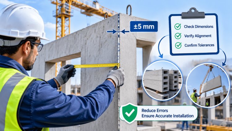
Tolerances in precast concrete are formally defined as the permissible variation from a specified dimension or position. They are not approximations or guesses — they are engineered limits that account for the inherent variability in materials, forming, curing, and handling. The primary industry references governing these limits are PCI MNL-135 (Fabrication and Shipment Tolerances) and ACI 117 (Specification for Tolerances for Concrete Construction).
Manufacturing Tolerances
Manufacturing tolerances govern the as-cast dimensions of the element as it leaves the precaster's plant. Key parameters include:
These values represent maximum permissible deviations — not targets. A quality fabricator aims for far tighter actual production variation.
Erection Tolerances
Erection tolerances apply to the installed position of the element relative to the structure. They are typically larger than fabrication tolerances because field conditions introduce additional variables: substructure deviations, crane positioning, temporary bracing behavior, and thermal movement.
Understanding the distinction between these two tolerance categories is foundational to every precast coordination meeting and contract specification review.
Critical Design Principle
Manufacturing tolerances and erection tolerances are additive in design. Connections, bearing seats, joint widths, embeds, and adjustment details must be sized to accommodate the worst-case combination of both tolerance categories — not either one in isolation.
Why the Distinction Matters
Fabrication tolerances determine whether a panel is acceptable leaving the plant.
Erection tolerances determine whether a panel is acceptable after installation.
Successful detailing accounts for both simultaneously, ensuring that joints remain functional, connections remain installable, and façade alignment remains visually acceptable even when all permissible tolerances are present.
Tolerances are not defects. They are engineered allowances that must be anticipated, coordinated, and accommodated throughout design, fabrication, and erection.
Even when individual precast elements fall within their specified tolerances, the assembly as a whole can accumulate deviations that create significant installation problems. Accumulated tolerance is the compounding of multiple individual variations — and it is the most common source of precast field conflicts on complex structures.
Alignment tolerances govern the relative position of adjacent precast units and their relationship to the structure's theoretical grid. Elevation control is especially critical at bearing conditions, where even minor deviations in bearing seat height translate directly into misalignment of spandrel faces, double-tee flanges, and hollow-core floor levels. Best practices include:
Establish primary control benchmarks at column lines before erection begins
Survey each bearing condition prior to element placement
Use leveling plates and shim stacks to achieve precise bearing elevation
Verify plumb of wall panels at each story before proceeding to the next level
Check differential elevation between adjacent horizontal units before grouting joints
Connections must be designed with sufficient clearance to accept elements that are at the allowable tolerance limit. A connection that works perfectly for a theoretically sized element but fails when fabrication and erection tolerances stack unfavorably is an engineering deficiency, not a field problem. Design clearances should account for:
Anchor bolt group location tolerance (±1 in. typical)
Weld plate positioning (±1/2 in. typical)
Slotted holes sized for full tolerance range plus adjustment
Grouted pocket dimensions that allow for angular misalignment
When a precast frame consists of many sequential elements — consider a row of 20 double-tees spanning between two beams — each unit's individual tolerance deviation contributes to the total accumulated variation at the end of the run. This is sometimes called "tolerance stack-up."
Practical strategies to manage accumulation include:
Establish closure elements: Design one element in each bay or run as a field-cut closer that absorbs accumulated joint variation
Set reference points at intervals: Don't allow tolerances to propagate continuously — reset alignment to a control point every 5–6 elements
Use adjustable connections: Slotted embeds and adjustable seat angles provide field correction capability without rework
Pre-survey the supporting structure: Identify out-of-tolerance bearing conditions before delivery and correct them before erection begins
Statistical tolerance analysis: For complex assemblies, use root-sum-square (RSS) analysis rather than worst-case arithmetic stacking to predict realistic accumulated deviation
For additional guidance on structural coordination and sequencing, explore Consac.com's precast construction resources covering erection planning, connection design, and QC documentation frameworks.
Alignment, Elevation, Connection Clearances & Accumulated Tolerances
Alignment & Elevation Requirements
Connection Clearance Requirements
Managing Accumulated Tolerances Across Multiple Elements
Survey Structure
Verify Dimensions
Set Control Points
Adjust & Confirm
Building Information Modeling has transformed tolerance management from a reactive field activity into a proactive design-phase discipline. By integrating fabrication-accurate precast models with structural, MEP, and architectural models, project teams can identify dimensional conflicts, connection interferences, and tolerance-driven clearance issues weeks before steel is set or concrete is poured.
For teams building out their BIM coordination protocols, Consac.com provides detailed resources on precast model development standards, clash detection workflows, and digital quality control integration—supporting fabricators and erectors through every phase of the coordination process.
BIM-Based Coordination for
Identifying Dimensional ConflictsResolve conflicts before steel is set or concrete is poured.
Effective tolerance management requires more than specification compliance. It depends on disciplined procedures, trained personnel, calibrated measurement equipment, documented inspections, and continuous accountability throughout both fabrication and erection. The strongest precast projects establish quality control systems that identify issues early, document them thoroughly, and resolve them before they become field failures.
Every project should maintain a complete tolerance-management file from fabrication through final erection.
Maximum allowable deviation for many precast elements up to 40 feet in length.
Typical plan-position tolerance relative to theoretical structural grids.
Fabrication-ready BIM development including embeds and connection details.
Every precast element should receive dimensional verification with no sampling exceptions.
Tolerances are not simply acceptance criteria—they are an active management process that begins before casting and continues through final installation. Organizations that invest in disciplined measurement, documented inspections, engineering review procedures, and complete quality records consistently achieve better fit-up, fewer field modifications, reduced schedule risk, and higher overall project quality. The strongest quality programs do not detect problems after they occur—they prevent them from occurring in the first place.
Practical Quality Control Strategies for Fabrication & Installation
Fabrication Quality Controls
Erection Quality Controls
Documentation & Closeout Requirements
Final Quality Management Principle
What's Your Reaction?