Form Deck Detailing for Industrial Platforms
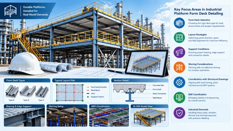
Industrial platform projects demand a level of precision in form deck detailing that goes far beyond standard commercial floor applications. Unlike conventional construction scenarios, industrial platforms must accommodate heavy dynamic loads, vibration-intensive equipment, elevated thermal and chemical exposure conditions, and complex interface requirements with structural steel framing, joists, and mechanical systems — all within tight erection sequencing constraints. This presentation dives deep into the discipline-specific detailing practices that experienced steel deck detailers and BIM coordinators must master when working on industrial platform structures — from proper form deck selection and layout strategies to support conditions, bearing requirements, shoring considerations, and coordination with structural drawings. It is a practitioner-level guide built for those who have moved beyond the basics and are navigating the real-world complexity of industrial deck production d
Understanding Form Deck in Industrial Context
Dead Load
Live Loads
Prior to Cure
Why Industrial Platforms
Are Different
Detailers working on power plants, petrochemical structures, offshore topsides, and heavy manufacturing platforms encounter conditions that fundamentally alter standard form deck detailing assumptions.
Proper form deck detailing on industrial platforms is principally driven by three interdependent technical domains: deck panel layout and orientation, bearing conditions at supports, and the interface with primary and secondary structural framing. Errors in any one of these areas can generate costly RFIs, erection delays, or—in worst cases—structural deficiencies during concrete placement.
When slab thickness and wet concrete weight exceed the unshored span capacity of the selected form deck, intermediate shoring must be detailed. The deck drawing set should include a dedicated shoring plan showing shore locations, allowable post loads, and stripping sequence tied to concrete cure schedule.
Proper form deck detailing on industrial platforms is principally driven by three interdependent technical domains: deck panel layout and orientation, bearing conditions at supports, and the interface with primary and secondary structural framing. Errors in any one of these areas can generate costly RFIs, erection delays, or structural deficiencies during concrete placement. Five critical detailing requirements govern industrial platform form deck: (1) Panel Layout & Orientation Strategy—the orientation of form deck flutes relative to support framing must be clearly communicated on every deck plan; on industrial platforms, flutes run perpendicular to the supporting beams or joists in standard configurations (this is the assumed direction for all published span table values); detailers must flag and engineer any condition where constraints force a parallel-to-support orientation as slab spanning assumptions change fundamentally; end laps must land on a structural support with minimum 1½" bearing per ANSI/SDI specification; side laps must be fastened per diaphragm design requirements called out on structural drawings; layout should begin from a control line established by the structural engineer (not from a column face) to maintain consistent module across the platform; edge conditions at platform perimeter, penetrations, and slab blockouts require closure strips, pour stops, and angle closures detailed at correct height relative to top of slab elevation; when supporting beams are skewed relative to deck run direction, triangular filler pieces or field-cut panels must be detailed with clear cut-line dimensions and fastening requirements. (2) Bearing Conditions at Structural Supports—form deck must bear positively on each support member; minimum 1½" end bearing is the SDI minimum, though on industrial platforms where vibration or thermal cycling is expected, detailers should coordinate with the structural engineer on whether increased bearing or positive attachment at every flute valley is required; when beam flange widths are narrow (e.g., W8 or W10 sections), the detailer must verify that minimum bearing is achievable without requiring both sheet ends to share a single narrow flange; puddle welds (typically 5/8" diameter arc spot welds) or powder-actuated fasteners are specified at each support; the pattern (e.g., 36/7) must match the diaphragm calculation or be explicitly noted as "by EOR"; where form deck bears on open-web steel joists, deck attachment must avoid bridging rows and account for joist chord geometry to ensure positive weld contact without arcing on chord angles. (3) Shoring Plan Coordination—when slab thickness and wet concrete weight exceed the unshored span capacity of the selected form deck, intermediate shoring must be detailed; the deck drawing set should include a dedicated shoring plan showing shore locations, allowable post loads, and stripping sequence tied to concrete cure schedule—this is not optional documentation but a contractual deliverable on most industrial projects. (4) Edge Angle & Pour Stop Selection—at slab edges, pour stops must match the top-of-slab elevation exactly; on industrial platforms with variable slab thickness zones (e.g., equipment pads vs. standard platform slab), multiple pour stop heights may appear within the same bay; each transition must be detailed with a section cut showing the step condition, the pour stop profile, and the attachment to the perimeter framing. (5) Headed Stud Clearance (Even Without Composite Action)—even when form deck is non-composite, structural engineers on industrial platforms occasionally specify headed studs on beams below the slab for connection of grating, checker plate covers, or secondary steel; detailers must confirm stud height-to-deck profile clearance and flag any conflicts with flute geometry, particularly at 1½" deck where stud height restrictions are most binding.
Critical Detailing Requirements:
Layout, Bearing & Support ConditionsCritical Detailing Requirements Summary
Domain
Key Requirement
Standard/Specification
Common Error
Panel Layout & Orientation
Flutes perpendicular to supports (standard); end laps on structural supports with min 1½" bearing; layout from control line (not column face)
ANSI/SDI specification; published span tables assume perpendicular orientation
Parallel-to-support orientation without engineering; end laps between supports; layout from column face instead of control line
Bearing Conditions
Min 1½" end bearing (SDI); puddle welds or PAFs at each support; pattern must match diaphragm calculation or be noted "by EOR"
SDI minimum 1½" bearing; diaphragm design requirements on structural drawings
Both sheet ends sharing single narrow flange; attachment pattern not matching diaphragm calculation; arcing on joist chord angles
Shoring Plan
Dedicated shoring plan required when wet concrete weight exceeds unshored span capacity; show shore locations, allowable post loads, stripping sequence tied to cure schedule
Contractual deliverable on most industrial projects; stripping sequence tied to concrete cure schedule
No shoring plan provided; stripping sequence not tied to cure schedule; premature shore removal causing slab cracking
Edge Angle & Pour Stops
Pour stops must match top-of-slab elevation exactly; variable slab thickness zones require section cuts showing step condition, pour stop profile, and attachment
Top-of-slab elevation must be matched exactly; section cuts required for transitions
Pour stop height not matching top-of-slab elevation; no section cuts for variable slab thickness transitions; field crews interpreting variable conditions without explicit detail
Headed Stud Clearance
Confirm stud height-to-deck profile clearance; flag conflicts with flute geometry; particularly critical at 1½" deck
Stud height must not interfere with deck ribs or prevent proper deck bearing
Studs conflicting with deck flute geometry; field modifications to studs or deck; compromised structural connections
Errors in Any One of These Areas Can Generate Costly RFIs, Erection Delays, or Structural Deficiencies During Concrete Placement
Dedicated Shoring Plan Is Not Optional Documentation—It Is a Contractual Deliverable on Most Industrial Projects
The Critical Detailing Principle
Every opening on an industrial platform deck plan should carry a unique tag referencing a coordination matrix that links to the responsible trade drawing.
Coordination failure to prevent: A penetration shown on the piping drawing but omitted from the deck plan can remain undiscovered until concrete is already placed.
Form deck must be modelled to LOD 350 or higher in Revit or Tekla, capturing exact deck profile, gauge, bearing conditions, edge closures, and opening locations. Generic deck families are insufficient — profile-accurate families that reflect actual cross-section geometry are required for reliable clash detection.
The deck model must participate in federated clash detection against the structural model for bearing and attachment conflicts, the MEP model for penetration conflicts, and the equipment model for clearance above deck and loading conflicts with shoring zones.
BIM execution plans should define a penetration freeze date — after which no new penetrations are added to the deck drawings without a formal RFI or design change notice. Detailers must advocate for this milestone early in the project schedule.
Each revision to the deck model should be cloud-marked and captured in the drawing revision block with a clear description. On large industrial projects with 10–30+ deck drawing sheets, revision traceability is a significant quality control requirement.
Where the BIM execution plan requires IFC exports for owner review or multi-discipline model federation, the deck model must be exported with correct IFC entity classifications (IfcSlab for the concrete slab, IfcPlate for form deck panels) and attribute data populated per the project's BIM data requirements.
Maintain a live coordination matrix crossreferencing every opening by tag number, responsible trade, deck drawing sheet reference, status (pending/confirmed/frozen), and slab reinforcing requirement.
Distribute the matrix to all disciplines at each BIM coordination meeting.
Use manufacturer-specific or accurately dimensioned deck profile families in Revit/Tekla.
Correct flute geometry is essential for clash detection and quantity takeoff. An incorrect profile depth can produce systemic area and weight miscalculations across the platform.
Review every form deck drawing sheet against a discipline-specific QC checklist covering:
Every opening should be identifiable, modelled, structurally supported, trade-coordinated, revision-traceable, and verified before construction release.
Detail the Void According to Its Structural Impact
Every Opening Needs a Coordination Identity
The Deck Model as a Coordination Control Layer
Model Authoring Standards
Clash Detection Responsibilities
Penetration Freezing Milestones
Revision Traceability
IFC Export & Interoperability
Keep Every Penetration Accounted For
Opening tag completeness
Pour stop elevation accuracy
Attachment pattern notation
Shoring plan cross-reference
Coating specification callout
Bringing all of the preceding technical requirements together into a disciplined, repeatable production detailing workflow is the defining competency of an experienced industrial platform deck detailer. The following summarises the end-to-end workflow and closes with the core principles that separate competent form deck detailing from genuinely excellent industrial platform documentation.
Confirm deck type, gauge, span direction, attachment pattern, shoring requirements, and coating specification directly from the structural engineer's deck specification sheet and general notes. Never assume conditions from previous projects because owner standards and EOR preferences vary significantly.
Establish control lines, load the correct deck profile families, reference supporting framing directly from the structural model, and lay out sheets with accurate end-lap and side-lap locations. Verify minimum bearing at each support before advancing further.
Import all discipline penetration lists, assign opening tags, model supplemental trimmer framing where required, and perform initial clash detection. Issue a penetration coordination report to the project BIM coordinator.
Generate plan views, sections, schedules, and details directly from the coordinated model. Apply the quality-control checklist and complete an internal peer review prior to formal EOR submission.
Issue IFC exports according to BIM execution plan requirements. Maintain revision tracking logs and process RFI responses and design change notices within 48 hours to avoid drawing-set lag on fast-track industrial projects.
Minimum 1½″ end bearing at every support must be verified analytically within the BIM model rather than assumed from general arrangement drawings.
Penetration coordination is often the longest-lead detailing activity. Begin coordination immediately and establish a penetration freeze date as early as practical.
If shoring is required, the shoring plan is a formal deliverable. Issue, review, revise, and track it with the same discipline applied to deck drawings.
Owner standards and project specifications frequently supersede SDI defaults. Review project requirements completely before beginning detailing work.
Form deck detailing on industrial platforms is a discipline where the quality of coordination documentation — penetration matrices, shoring plans, revision logs, BIM clash reports, and status tracking systems — is as important as the deck drawings themselves. Invest in process infrastructure as aggressively as production output. The strongest projects succeed because coordination is treated as an engineered deliverable rather than an administrative task.
Production Detailing Workflow & Key Takeaways
End-to-End Production Workflow
Stage 1 — Structural Review
Stage 2 — BIM Model Setup
Stage 3 — Opening Coordination
Stage 4 — Drawing Production
Stage 5 — IFC & Revision Management
Key Takeaways for Industrial Form Deck Practice
Final Industry Principle
What's Your Reaction?