Designing with Light Gauge Steel: Structural Considerations
Light gauge steel framing has transformed modern construction, offering unmatched strength-to-weight ratios and design flexibility. Understanding the structural nuances of this material is essential for engineers, architects, and builders who want to maximize efficiency while ensuring safety and compliance.

Why Light Gauge Steel Is Reshaping Modern Construction
|
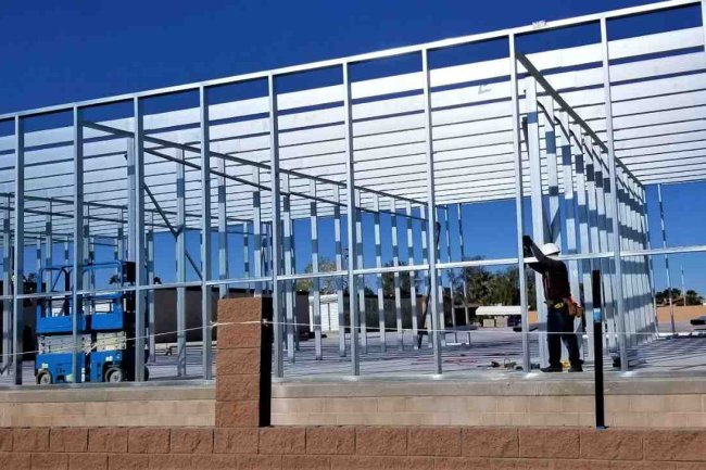
Light gauge steel (LGS) framing systems have become the backbone of contemporary building design, offering advantages that traditional materials simply cannot match. With cold-formed steel members typically ranging from 18 to 33 mils in thickness, these systems deliver exceptional structural performance while maintaining remarkable workability. The material's consistency eliminates concerns about warping, twisting, or shrinking—common issues with wood framing. This predictability translates to faster construction timelines and reduced callbacks, making LGS an increasingly popular choice for commercial, residential, and industrial projects across the United States. |
|
Critical Load Path Considerations
01 Gravity Load Distribution
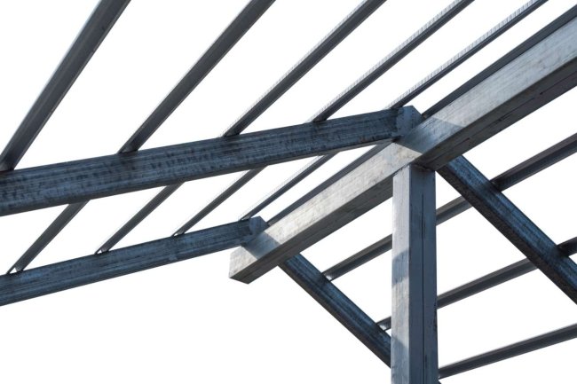
Understanding how vertical loads transfer through floor systems, wall studs, and foundation connections is fundamental. Properly sized members and strategic spacing ensure loads reach the ground safely.
02 Lateral Load Resistance
Wind and seismic forces require careful attention to shear wall design, diagonal bracing, and connection detailing. The load path must be continuous and clearly defined.
03 Connection Integrity
Every joint represents a potential weak point. Screw patterns, spacing, and edge distances must comply with manufacturer specifications and building codes to maintain structural integrity.
04 Load Transfer Mechanisms
Track-to-stud connections, header assemblies, and floor-to-wall interfaces require engineering analysis to verify adequate capacity for all anticipated loading conditions.
Member Selection and Sizing: Getting It Right
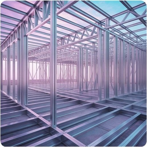
Selecting appropriate steel framing members involves balancing multiple factors: span requirements, load magnitude, deflection limits, and cost considerations. Engineers must account for both strength and serviceability limit states when specifying member dimensions.
Standard stud depths range from 2½ inches to 12 inches, with flange widths typically at 1½ inches. The key is matching member capacity to applied loads while considering factors like unbraced length, which significantly affects flexural and axial capacity. Web crippling and local buckling must also be evaluated, particularly at bearing points and concentrated load locations.
Span Optimization
Calculate required section modulus based on bending moments and deflection criteria.
Load Capacity
Verify both allowable stress design (ASD) and load resistance factor design (LRFD) values.
Stability Checks
Evaluate lateral-torsional buckling potential and web crippling at support points.
Thermal Performance and Bridging Solutions
The Challenge
Steel’s high thermal conductivity creates a significant challenge: thermal bridging. Continuous steel studs can reduce wall assembly R-values by 50% or more, undermining energy efficiency goals and potentially causing condensation issues within wall cavities.
This occurs because steel conducts heat roughly 400 times more effectively than wood, creating pathways for thermal energy to bypass insulation layers.
Proven Strategies
-
Exterior continuous insulation: Adding rigid foam sheathing outside the steel frame effectively breaks the thermal bridge.
-
Insulated cavity fill: High-density spray foam or mineral wool between studs reduces heat transfer.
-
Thermal spacers: Proprietary clips and channels physically separate interior finishes from steel members.
-
Strategic framing: Staggered or double-wall systems minimize continuous steel paths.
Connection Design: Where Engineering Meets Execution
Connections represent the most critical—and often most overlooked—aspect of light gauge steel design. Unlike welded heavy steel construction, LGS systems rely primarily on mechanical fasteners: self-drilling screws, bolts, and proprietary connectors. Each connection type has specific load capacities influenced by steel thickness, fastener diameter, edge distances, and spacing.
Screw Connections
Most common method. Verify shear, tension, and combined loading capacity. Minimum #8 screws for structural connections, with specific patterns for different load conditions.
Bolted Assemblies
Used for high-load transfers. Requires careful consideration of bearing, net section, and block shear failure modes. Oversized holes not permitted in structural applications.
Proprietary Systems
Pre-engineered connectors offer tested capacity values. Companies like Consac provide detailed engineering support and connection schedules that streamline the design-to-fabrication process.
Track-to-Foundation
Anchor bolts or powder-actuated fasteners must resist both shear and uplift. Spacing typically ranges from 24 to 48 inches based on load magnitude and seismic design category.
Engineering Success with Light Gauge Steel
Key Takeaways for Your Next Project
- ✔ Successful light gauge steel design balances structural performance, constructability, and cost efficiency. By understanding load paths, selecting appropriate members, addressing thermal bridging, and detailing connections properly, engineers can deliver projects that perform reliably for decades.
- ✔ The material's precision and consistency make it ideal for modern construction workflows, particularly when integrated with BIM and digital fabrication technologies.
- ✔ As building codes evolve and sustainability becomes increasingly important, light gauge steel framing will continue to play a central role in the built environment.
- ✔ Ready to optimize your next steel framing project? Partner with experienced engineering teams who understand both the technical requirements and practical realities of light gauge steel construction.
What's Your Reaction?