Roof Deck Detailing Near Clerestory Framing
Clerestory conditions represent one of the most demanding intersection points in roof deck design — where vertical glazing frames meet horizontal deck planes, creating complex structural, thermal, and sequencing challenges that generic detailing standards simply don't address. This guide walks structural engineers and BIM detailers through the critical decisions required at these junctions: bearing conditions, edge framing geometry, deck termination strategies, and coordination protocols that keep steel decking performance intact right up to the clerestory wall line.
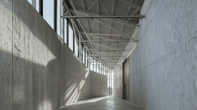
Why Clerestory Junctions Demand Special Attention
Standard roof deck details are developed around uninterrupted diaphragm conditions. Clerestory zones fundamentally disrupt that assumption. At these locations the roof diaphragm intersects a vertical structural element, creating a concentration of forces, complex framing transitions, unusual deck termination conditions, and demanding architectural coordination requirements. What appears architecturally simple often becomes one of the most detail-sensitive regions of the entire roof structure.
A Clerestory Creates a Break in the Roof Diaphragm
Diaphragm forces, framing geometry, deck attachment, glazing coordination, air barriers, and construction access all converge at the same location. Successful detailing requires every discipline to work from a coordinated solution.
Why Clerestory Zones Are High-Risk Areas
Chord Design Cannot Be Assumed
Clerestory wall lines often serve as diaphragm boundaries. Chord members, collector elements, connection welds, bolts, and supporting structural members should be explicitly detailed and sized rather than implied through typical deck details.
Structural and Architectural Coordination
Installation Order Matters
How the deck panel terminates at the clerestory bearing member is the single most consequential detailing decision in this zone. Three primary strategies exist, each with distinct structural implications: deck bears directly on the beam top flange, deck terminates at a ledger angle welded to the clerestory column or wall framing, or deck extends over and beyond the clerestory bearing member in a cantilever condition.
The most structurally efficient termination: deck panels run continuous to the beam top flange, providing direct bearing and enabling standard puddle weld or self-drilling screw (SDS) fastening patterns per the SDI Deck Design Manual.
Where the clerestory frame geometry prevents deck panels from reaching a beam top flange (e.g., inset glazing systems or curtain wall frames set inside the structural bay), a structural ledger angle welded to the column web or a supplemental tube/channel provides the deck bearing surface.
In certain roof geometries—particularly sawtooth or monitor roof profiles—the lower deck plane may extend past the clerestory bearing member to form a short cantilever before terminating at an edge fascia.
Beam flange ≥1½″ bearing width, flute closures at edge, angle chord welded to web face before deck, standard SDI fastening patterns.
L4×3½×5/16 minimum angle, weld designed for deck reaction + chord force + concentrated loads, BIM interference checks with glazing.
Negative moment capacity check, uplift fastener capacity at root, cantilever ≤½ adjacent span or manufacturer max, amplified chord forces.
Deck hosted element precisely terminated at beam face with separate closure element modeled at flute end. Structural angle chord welded to beam web face before deck installation.
Ledger angle placed as structural member—not generic detail component. Deliberate interference checks against glazing system framing required to capture conflicts before construction.
Cantilever deck modeled extending past bearing member with edge fascia detail. Negative moment and uplift capacity must be explicitly called out in structural notes.
All strategies require precise deck termination modeling, explicit fastener patterns, and coordination with architectural glazing and curtain wall systems.
How the deck panel terminates at the clerestory bearing member affects bearing, fastening, chord forces, and BIM coordination.
How the deck panel terminates at the clerestory bearing member is the single most consequential detailing decision in this zone. Strategy 1—deck bears directly on beam top flange—is most structurally efficient with standard SDI fastening and 1½″ minimum bearing. Strategy 2—ledger angle welded to column or wall framing—accommodates inset glazing systems with L4×3½×5/16 minimum angle designed for combined loads. Strategy 3—cantilever beyond bearing member—requires negative moment capacity checks, uplift fastener verification, and EOR confirmation of amplified chord forces. Each strategy has distinct BIM modeling requirements and coordination implications with glazing systems. The choice must be made early and coordinated across structural, architectural, and glazing disciplines.
Deck Termination Strategies at the Clerestory Wall Line
Deck Bears Directly on Top Flange of Spandrel/Collector Beam
• Beam top flange wide enough for minimum 1½″ bearing
• Standard puddle weld or SDS fastening per SDI
• Flute closures at beam flange edge
• Prevent air infiltration and maintain fire-rated continuity
• Deck hosted element precisely terminated at beam face
• Separate closure element modeled at flute end
• Structural angle chord welded to beam top flange web face
• Angle welded before deck installation—not on top of deckDeck Terminates at a Ledger Angle Welded to Clerestory Column or Wall Framing
• Minimum angle leg size: L4×3½×5/16 or per project design
• Horizontal leg provides bearing surface
• Welded to column web or supplemental tube/channel
• Designed for deck reaction + chord force + concentrated loads
• More difficult to model accurately
• Angle placed as structural member—not generic detail
• Interference checks against glazing system framing required
• Deliberate coordination with curtain wall or inset glazingDeck Extends Over and Beyond the Clerestory Bearing Member (Cantilever Condition)
• Explicit negative moment capacity in deck span tables
• Deck-to-frame fastener capacity for uplift at cantilever root
• Separate edge trim detail at fascia
• Chord forces at clerestory bearing amplified—confirm with EOR
• Generally limited to lesser of ½ adjacent span
• Or panel manufacturer's published maximum
• Uplift at cantilever root critical
• Edge fascia detail requiredStrategy Comparison Table
Criteria
Strategy 1: Direct Bearing
Strategy 2: Ledger Angle
Strategy 3: Cantilever
Structural efficiency
Most efficient
Moderate
Least efficient
Bearing requirement
1½″ min on beam flange
L4×3½×5/16 angle
Negative moment check
Fastening
Standard puddle weld/SDS
Angle weld design
Uplift at cantilever root
BIM complexity
Simplest
More difficult
Moderate
Use cases
Standard conditions
Inset glazing, curtain wall
Sawtooth, monitor roofs
Chord forces
Standard
Combined with angle
Amplified—EOR review
Critical Detailing Requirements by Strategy
BIM Modeling Considerations
Strategy 1: Simplest
Strategy 2: More Difficult
Strategy 3: Moderate
General Requirements
The Single Most Consequential Detailing Decision
The Termination Principle
Clerestory framing requires explicit detailing of spandrel beams, chord angles, and columns. Fastener density, weld accessibility, and load path coordination must be resolved early in design to prevent field conflicts and ensure diaphragm continuity.
Framing Member Sizing & Connection Detailing
Structural Members at the Clerestory Interface
Fastening & Weld Pattern Requirements
Key Insight
Clerestory roof intersections represent one of the most clash-prone locations in a structural BIM model. Within a narrow vertical band, structural steel, roof deck terminations, glazing support framing, roofing assemblies, insulation systems, edge closures, and MEP penetrations compete for space. Effective BIM coordination transforms these areas from construction risks into fully resolved digital assemblies before steel fabrication and roof installation begin.
Structural framing, roof deck, clerestory glazing, roofing components, and MEP systems intersect at the same elevation. Even minor modeling inaccuracies can generate fabrication conflicts, installation delays, and costly field modifications.
Modeling the chord angle as a true structural member allows clashes to be detected against clerestory columns, base plates, mullions, insulation systems, roof edge components, and deck supports long before construction begins.
Installing glazing before deck terminations, closure strips, chord angles, or weld completion frequently eliminates access to critical connection locations and often forces expensive field substitutions.
BIM Coordination at Clerestory Deck Zones
Five Building Systems Converge at One Location
Why Clerestory Zones Generate Clashes
Generic Families Hide Real Problems
Model Closure Elements Explicitly
Glazing Installed Too Early
Before issuing roof deck drawings and BIM models that include clerestory framing zones, confirm the following items are explicitly addressed. This checklist reflects the most common omissions found in structural drawing reviews at clerestory conditions. Clerestory framing zones reward careful detailing discipline—the structural decisions made at this intersection directly determine whether the deck performs as a diaphragm element, whether the construction sequence is executable, and whether the glazing system can be installed without costly field modifications.
Define support locations and loads. Select deck termination strategy (direct bearing, ledger angle, or cantilever) and coordinate with architectural elevations.
Specify chord sizes and connections. Show chord angle or drag strut on framing and deck plans with weld length and splice locations.
Align models with shop and site data. Model chord angles as structural elements, terminate deck at actual bearing elevation, run clash detection.
Verify erection and installation steps. Capture installation sequence in model phasing, coordinate with glazing subcontractor, resolve RFIs before shop drawing approval.
Deck termination strategy left to field interpretation instead of being explicitly called out on framing plan.
Chord angle or drag strut shown on framing plan only—not on deck plan, or size and weld length omitted.
Spandrel beam top-of-steel not coordinated against clerestory sill elevation and deck panel slope.
Perimeter weld/fastener spacing at clerestory bearing not distinguished from field spacing on deck plan legend.
Chord angle modeled as annotation or generic model instead of structural framing element in clash detection scope.
Coordination review with glazing/curtain wall subcontractor not documented, RFIs unresolved before deck shop drawing approval.
The structural decisions at the clerestory intersection directly determine whether the deck performs as a diaphragm element under lateral loads.
Proper detailing and BIM coordination determine whether the construction sequence is executable without field workarounds.
Early coordination with glazing contractors prevents costly field modifications to curtain wall or inset glazing systems.
Bearing strategy, chord design, fastener patterns.
Model fidelity, clash detection, phasing.
Shop drawings, fastener specs, closures.
Curtain wall interface, sill elevations.
The structural decisions made at this intersection directly determine diaphragm performance, construction sequence, and glazing installation.
Clerestory framing zones reward careful detailing discipline. Before issuing drawings and BIM models, confirm deck termination strategy is explicitly called out on framing plans, chord angles are shown on both framing and deck plans with size and weld length, spandrel beam elevations are coordinated against clerestory sill and deck slope, perimeter fastener spacing is distinguished from field spacing, flute closures are detailed at 1:10 scale, chord angles are modeled as structural framing elements in clash detection scope, deck panels are terminated at actual bearing surface elevation, and coordination with glazing contractors is documented with RFIs resolved before deck shop drawing approval. The structural decisions made at this intersection—bearing strategy, chord member continuity, fastener density, and BIM model fidelity—directly determine whether the deck performs as a diaphragm element, whether the construction sequence is executable, and whether the glazing system can be installed without costly field modifications. Early coordination between the structural engineer, BIM detailer, deck supplier, and glazing contractor is not optional at clerestory conditions—it is the baseline requirement for a constructable detail.
Key Detailing Takeaways & Drawing Checklist
Structural Drawing Checklist
BIM Model Checklist
The Four-Step Clerestory Workflow
Bearing Strategy
Detail Chords
Coordinate BIM
Confirm Sequence
Common Omissions at Clerestory Conditions
Deck Termination Undefined
Chord Angle Missing from Plans
Elevation Conflicts
Fastener Spacing Ambiguous
Chord Angle Not Modeled
Glazing Coordination Late
Why This Coordination Matters
Coordination Stakeholders
Clerestory Framing Zones Reward Careful Detailing Discipline
The Clerestory Principle
What's Your Reaction?