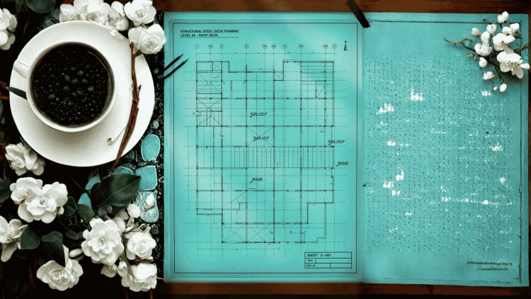
Steel Deck Pre-Layout Verification
Why Pre-Layout Verification Matters
The Most Expensive Mistakes Begin with Incorrect Assumptions
Grid lines and elevations form the foundation of every deck layout. When these references are misunderstood, every downstream detail—from joist locations to pour stops and bearing conditions—can be affected. Pre-layout verification ensures the model begins from verified project reality rather than assumptions.
The Pre-Layout Verification Ladder
Step 1
Review Structural Grid Documents
Step 2
Verify Elevation Benchmarks
Step 3
Check Bearing Elevations
Step 4
Identify Discrepancies
Step 5
Document & Communicate Findings
Where a Small Error Can Lead
Paper Review
Minutes to Resolve
Field Discovery
Days or Weeks to Resolve
Layout Accuracy Starts with Verified References
DECK LAYOUT
Bearing Verification
Elevation Confirmation
Structural Grid Validation
What This Guide Covers
Grid Documents
Benchmarks
Bearing Checks
Conflict Detection
EOR Communication
GRID
Verification Principle
Verify the Foundation Before Drawing the Layout
Every successful deck layout begins with confirmed grids, validated elevations, and verified bearing conditions. A structured pre-layout review transforms costly field surprises into inexpensive design-stage corrections and creates a reliable foundation for the entire detailing process.
Step 1
Gather and Cross-Reference Grid Documents
Before a single deck panel is placed, confirm that the grid information used in the deck layout matches the governing structural documents without assumption.
01
Identify the Governing Structural Drawing Set
Start with the issued-for-construction structural drawings, not preliminary or design-development sets. Confirm the revision level and record the revision date on the layout cover sheet for traceability.
02
Locate the Grid Bubble Reference Plan
Pull the key plan showing alphanumeric grid lines and compare bay dimensions, north orientation, column offsets, and spacing against your digital model or CAD file.
03
Verify Against Architectural and Civil Drawings
Cross-check structural grid lines against architectural floor plans and civil site plans. Watch for face-of-finish and survey-control offsets, especially at perimeter conditions, stair openings, and curtainwall interfaces.
A
Why This Step Matters
Grid discrepancies are among the hardest layout errors to trace later. Catching revision drift, bay mismatches, and offset conflicts early prevents bearing layout problems and keeps the deck package aligned with the governing documents.
Step 2 • Pre-Layout Verification
Verify Elevation Benchmarks and Bearing Heights
One Incorrect Elevation Affects Everything Above It
Grid lines establish horizontal position, but elevations establish structural reality. Incorrect bearing elevations impact joist seats, deck planes, camber, finished floor levels, and MEP clearances simultaneously. Every vertical reference must be validated before layout begins.
The Vertical Control Stack
DECK BEARING SURFACE
JOIST TOP CHORD
JOIST SEAT DEPTH
TOP OF STEEL (TOS)
PROJECT DATUM / BENCHMARK
Four Critical Elevation Checks
1. Benchmark Verification
Confirm whether elevations are based on NAVD 88, MSL, or a project-specific benchmark.
2. TOS Extraction
Compile top-of-steel elevations from framing plans and schedules.
3. Joist Seat Validation
Verify seat depth places top chord at the intended bearing elevation.
4. Wall & Edge Bearing Check
Confirm perimeter and masonry bearing conditions align with adjacent steel framing.
How a Small Elevation Error Cascades
Incorrect Benchmark Interpretation
↓
Wrong TOS Elevation
↓
Deck Plane Misalignment
↓
Field Rework & Coordination Problems
Recommended TOS Tracking Format
Organize top-of-steel elevations by grid intersection and verify every supporting member before layout.
High-Risk Mistake
Never Assume Uniform Elevation
Multi-level roofs, stepped floor systems, transfer girders, and architectural transitions frequently create localized elevation changes. Every TOS value must be verified individually rather than assumed from adjacent framing.
TOS
Step 2 Principle
Build the Vertical Reference Chain Before the Layout
Reliable deck layouts depend on verified benchmarks, confirmed TOS elevations, validated joist seats, and coordinated bearing conditions. When the elevation chain is confirmed first, deck alignment, floor elevations, and construction tolerances become predictable and controllable.
Step 3 • Pre-Layout Verification
Identify and Document Discrepancies
The Goal Is Not to Fix Problems — It Is to Find Them
Pre-layout review is an investigative process. When conflicts are identified between grids, elevations, framing plans, and schedules, the detailer must document the issue, assess the impact, and obtain clarification from the Engineer of Record before layout proceeds.
Discrepancy Command Board
DETECT
Review drawings and identify conflicts
LOG
Record location, source, and impact
ESCALATE
Submit RFI to Engineer of Record
RESOLVE
Attach response and continue layout
High-Frequency Conflict Areas
REVIEW
ZONE
Grid Offset Conflicts
Grid origins do not align
Elevation Steps
TOS transitions missing
Missing TOS Notes
Bearing elevations unclear
Joist Schedule Conflicts
Plan and schedule mismatch
Required Discrepancy Log Fields
Location
Description
Source Docs
Impact
Status
The Golden Rule
STOP & ASK
If a condition cannot be verified directly from the contract documents, do not proceed based on assumptions. Submit an RFI and obtain written clarification before continuing layout work in the affected area.
The Cost of an Unanswered Question
Paper Review
RFI Stage
Field Correction
RFI
Step 3 Principle
Assumptions Create Rework. Documentation Creates Clarity.
Successful layout begins with verified information. Every discrepancy should be documented, escalated, tracked, and resolved through formal communication. Questions answered before layout take hours to resolve; unanswered questions discovered during erection can delay an entire project.
Pre-Layout Gate
Pre-Layout Verification Checklist & Next Steps
Use this quick-reference gate before any deck layout begins. Every item should be confirmed and initialed by the detailer or lead designer before panel layout starts.
01
Grid Document Review
IFC drawing set confirmed at current revision. Grid lines verified in CAD or model against the structural key plan. Irregular bays, skewed grids, and expansion joints are flagged before layout starts.
02
Elevation Datum Confirmed
Project datum identified as NAVD 88 or project-specific. Top-of-steel elevations are confirmed as absolute or relative to finished floor, with no mixed reference systems in layout files.
03
TOS Elevation Table Compiled
Top-of-steel elevations are extracted for all supporting members in the layout zone and checked against the member schedule. Multi-level steps are cross-checked across framing plan sheets.
04
Joist Seats & Bearing Verified
Joist seat depths are confirmed against SJI standards and the project schedule. Wall and edge bearing elevations are checked against masonry or concrete drawings and bearing plate details.
05
Discrepancy Log Cleared
All conflicts are documented in the discrepancy log, open items are submitted as RFIs to the EOR, and no layout assumptions are made pending written resolution. The log should be attached to the layout package.
Next Step
Completing this checklist before layout begins is the single highest-leverage action a detailer or deck designer can take to protect project quality. It turns pre-layout verification into a proactive discipline that reduces RFIs, rework, and schedule risk.