Steel Deck Detailing for Catwalk and Maintenance Areas
Loads, connections, edges, and drawing release. This deck walks steel detailers and drafters through the key decisions for catwalk and maintenance-area steel decking. It focuses on what to show on the drawings and what to check before release.
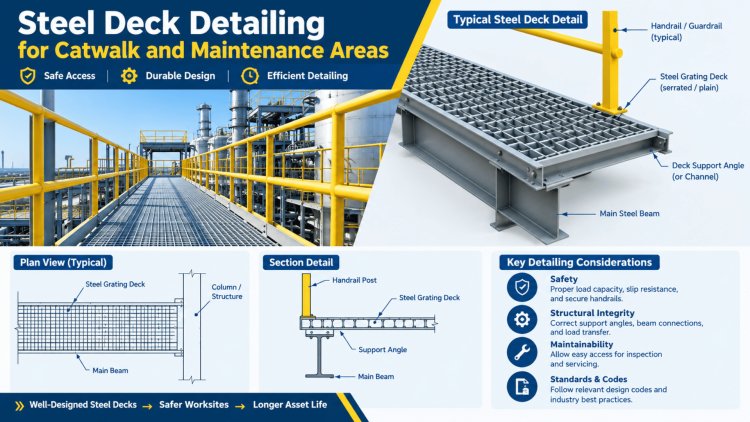
Design Basis
Catwalk decks carry different loads than roof decks
Establish Intended Use Before Selecting Loads, Deck Capacity, And Detailing Requirements
Definition
Criteria
System
Catwalk Loading Is Commonly Defined By Operational Use
Confirm Structural Requirements Before Detailing
Confirm live load and deflection limits with the engineer before detailing.
Confirm Performance Criteria Before Production Drawings
Locate Zones
Mark catwalk zones clearly on the deck plan.
Clearly Differentiate Catwalk Areas
Do Not Carry Roof-Deck Assumptions Into Maintenance Access Areas
Identify Use. Confirm Criteria. Define Zones.
Support and connection details keep the deck stable. Show bearing length and support spacing at framing lines, define fastener patterns at ends and sidelaps per the engineer’s requirements, and detail catwalk framing attachment to deck supports.
Show bearing length and support spacing at framing lines. Clearly documenting these conditions ensures the deck bears positively on each support and helps prevent erection errors, inadequate bearing, and downstream RFIs.
Show the fastener pattern at deck ends and sidelaps, per the engineer’s requirements. Fastening details govern diaphragm performance, uplift resistance, and field inspection—so spacing, fastener type, and location must be explicit.
Detail the attachment of catwalk framing to deck supports. This connection must be resolved with the supporting structure to maintain stability, transfer loads correctly, and avoid conflicts between catwalk members and deck installation.
Supports and
AttachmentsDeck Bearing
FRAMING LINESDeck Fastening
ENGINEER REQUIREMENTSFraming Attachment
CATWALK INTERFACE
Edges and openings need their own details. Resolve perimeter closures, penetration reinforcement, and handrail attachments before drawings are released.
Each edge and penetration condition should be clearly located and referenced in the detailing package.
Detail edge angles, closures, and toe plates at open sides.
Show reinforcement around small penetrations for access hatches and equipment.
Provide clear call-outs for handrail post attachments.
Verify that open sides, access penetrations, and handrail post attachments are shown with clear locations and detail references before drawing release.
Perimeter and Penetrations
Perimeter Edge Conditions
Opening Reinforcement
Attachment Call-Outs
Check the drawings before release
Verify drainage and slip-resistant finish notes.
Flag open questions to the engineer early.
Drawing Release
Review Coordination, Verify Requirements, And Resolve Outstanding Questions Before Issuance
Keep Related Components On A Single Coordinated Sheet
Confirm Critical Notes Before Release
Review Safety And Maintenance Requirements
Resolve Questions
Surface Uncertainty Before It Becomes Rework
Keep Unresolved Design Requirements Visible Before Release
Coordinate. Verify. Resolve. Release.
What's Your Reaction?