Non-Composite Deck Layout Coordination with Joists
A practical technical guide for structural engineers, steel deck detailers, and BIM coordinators on achieving precise, code-compliant layout alignment between noncomposite metal deck panels and the steel joist framing systems beneath them.
What Is Non-Composite Deck and Why Does Layout Matter?
Non-composite metal deck — commonly specified as form deck or structural deck without shear studs — serves primarily as a permanent formwork for concrete slabs. Unlike composite deck systems, non-composite deck does not rely on mechanical interlock or shear connectors to achieve composite action with the concrete. The deck carries wet concrete loads during construction and transfers finished slab loads through direct bearing on joists and beams, not through interface shear.
Because the structural mechanism is fundamentally different, layout coordination with the underlying joist framing becomes a critical detailing discipline in its own right. Every panel edge, every end lap, and every flute direction decision directly affects bearing adequacy, fastener placement, load path integrity, and the efficiency of the concrete pour above.
Poor layout coordination introduces risks ranging from inadequate end bearing (which can trigger panel uplift or rotation under construction loads) to misaligned pour stops and costly field rework. For detailers working in BIM environments, unresolved layout conflicts that surface in the field are exponentially more expensive than those caught at the coordination stage.
Learn more about the full spectrum of metal deck types and specifications covered across Consac's technical blog library.
Every panel edge, every end lap, and every flute direction decision directly affects bearing adequacy, fastener placement, load path integrity, and the efficiency of the concrete pour above.
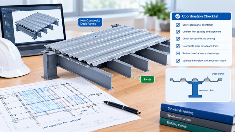
The single most critical layout variable is the relationship between joist spacing and deck panel coverage width. Non-composite deck panels are manufactured in standard coverage widths — most commonly 24″, 30″, and 36″ — and joist spacings are typically set at 4′-0″, 5′-0″, or 6′-0″ on center. When these two dimensions are not modular multiples of each other, partial panels, field cuts, or shifted grid origins become necessary — and each of these conditions must be explicitly detailed in the deck layout drawing.
Begin every deck layout by establishing a reference grid tied to joist centerlines. Map all joist spacings across the bay before placing a single deck panel. Identify modular runs versus non-modular conditions and flag them for engineering review early in the detailing cycle.
Non-composite deck ribs typically run perpendicular to joist spans. Confirm flute orientation against the structural engineer's intent — some roof deck applications run ribs parallel to supports, which changes bearing and fastening requirements entirely.
When a partial panel is unavoidable, position the cut panel at the bay perimeter — never at mid-bay — to avoid placing a cut edge over a joist top chord where fastener engagement may be compromised. Document all cut panels explicitly on the layout drawing with dimensions and orientation notes.
After panel placement is mapped, run a bearing verification check across all panel ends. Minimum bearing of 1½″ on steel framing is a code floor, not a target. Many specifications and deck manufacturers require 2″ minimum. Any bearing shortfall must be resolved before issuing for construction.
Joist Spacing, Panel Widths, and the Coordination Grid
Establish the Coordination Grid
Select Panel Orientation
Manage Panel Cuts Strategically
Verify End Bearing Continuously
Fastening patterns for non-composite deck serve a dual purpose: structural attachment that resists construction-phase uplift and in-plane diaphragm shear, and permanent attachment that satisfies wind uplift requirements for the finished building. The structural engineer’s diaphragm design specifies fastener type, spacing at supports (frame fasteners), and side lap spacing—and the deck layout detailer must ensure that every fastener location shown in the pattern can actually be executed in the field without conflict.
When joist spacing is non-modular relative to panel width, flute alignment shifts. Catch the conflict at the layout stage, not in the field.
Fastening Patterns: From
Diaphragm Design to Field RealityFasteners must land over joist top chords—not flute valleys.
Modern non-composite deck layout coordination is increasingly executed within BIM platforms — Revit, Tekla Structures, and SDS/2 being the most common environments for structural steel and deck detailing. The power of BIM for deck-joist coordination lies not in automated placement, but in the ability to run systematic clash detection and spatial verification across the full layout before a single shop drawing is issued.
In any BIM environment, the joist framing model must be complete and coordinated — including top chord elevations, bridging rows, and end bearing conditions — before deck panel placement begins. Placing deck panels against an incomplete or approximate joist model creates false coordination confidence and frequently results in field conflicts.
Joist top chord widths must be modeled accurately because they directly affect the usable bearing surface available for deck ends and fastening requirements. Accurate framing geometry is the foundation of reliable BIM coordination.Reference Consac's joist and deck coordination resources for guidance on modeling joist geometry correctly After deck panels are placed, automated clearance reviews should verify minimum bearing at all panel ends. Most BIM platforms support configurable rule sets that can automatically identify insufficient bearing conditions before detailing progresses.
A 1½-inch minimum bearing rule should be treated as a hard acceptance criterion, while a 2-inch threshold may be used as an early warning review filter. At the same time, verify deck panel edges against joist bridging locations that may interfere with planned installation sequencing.
Non-composite deck layout drawings must be coordinated with pour stop locations and slab-edge detailing. Because these elements are frequently tied directly to beam and joist framing lines, they should be modeled and reviewed as part of the BIM coordination process rather than treated as secondary construction details.
A pour stop that lands at a mid-panel condition rather than a panel termination can create concrete-retention challenges, require supplemental forming, and introduce unnecessary cost and schedule impacts. All pour-stop-to-panel-end conflicts should be resolved before construction documents are issued.
BIM does not eliminate coordination challenges; it moves them into a controlled environment where they can be identified and resolved before fabrication begins. The greatest value of BIM for deck and joist layouts comes from systematic verification of bearing conditions, installation clearances, edge detailing, and pour-stop coordination long before those issues become field conflicts, RFIs, schedule impacts, or costly rework.
BIM Coordination: Resolving Conflicts Before They Reach the Field
Model the Joist Grid First
in BIM workflows.
Run Bearing and Clearance Checks
Coordinate with Pour Stops and Edge Conditions
BIM Coordination Workflow
Field Coordination Principle
Non-composite deck layout coordination with joists is a precision discipline that sits at the intersection of structural engineering intent, fabrication geometry, and field constructibility. The risks of under-coordinated layouts — insufficient bearing, misaligned fasteners, conflicting pour stops, and diaphragm capacity shortfalls — are all preventable when a systematic coordination process is followed from the earliest stages of detailing.
The most successful project teams treat deck layout not as a downstream drafting task, but as an integrated coordination activity that involves the structural engineer of record, the deck and joist detailer, and the BIM coordinator working in parallel — not in sequence. Issues resolved at the layout drawing stage cost a fraction of what they cost when discovered during erection or concrete placement.
For broader technical context on joist design principles and how they intersect with deck specifications, explore Consac's complete library of structural steel and deck engineering resources.
Non-composite deck coordination is not a one-time check — it is an iterative review process that should be revisited every time the structural model or joist layout is updated during the design development cycle.
Key Takeaways and Coordination Checklist
Issues resolved at the layout drawing stage cost a fraction of what they cost when discovered during erection or concrete placement.
What's Your Reaction?