Form Deck Sheet Length Planning for Efficient Handling
Selecting the right sheet length for form deck is one of the most consequential — and frequently underestimated — decisions in structural steel detailing. While gauge, rib profile, and coating specifications often dominate early design conversations, sheet length directly governs how deck is transported, lifted, staged, and installed on the jobsite. A poorly planned length strategy cascades into field waste, safety risks, crane delays, and costly re-orders. This presentation distils the core principles of form deck sheet length planning into actionable guidance for structural engineers, detailers, and construction project managers. From standard sheet spans and transport constraints to field sequencing and coordination with joist layouts, every slide is designed to help you make smarter, site-ready decisions — before steel hits the floor.
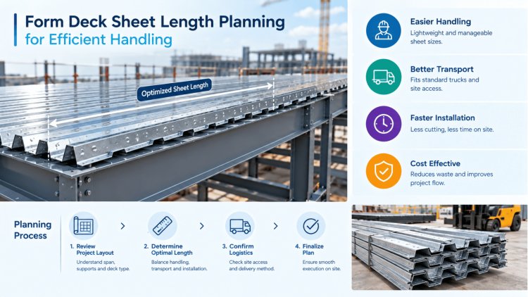
Understanding Sheet Length Standards & Transport Constraints
Longer sheets — those exceeding 30 ft — offer fewer end laps, reduce the number of puddle welds or mechanical fasteners required, and minimise edge-condition waste at slab edges. However, they introduce significant handling challenges: increased deflection during lifting, greater wind sail area during placement, and strict transport permitting requirements once lengths exceed standard flatbed capacity (typically 48 ft over-the-road).
Freight and Delivery Logistics
Sheets up to 40 ft can typically ship on standard flatbeds without special permits in most U.S. states — verify state DOT rules early
Oversized loads (length or bundle weight) require pilot cars, route surveys, and advance scheduling that can add 2–4 weeks to lead time
Bundle weight limits (commonly 4,000–6,000 lbs per bundle) often govern how long a sheet can be before crane pick counts increase significantly
Interior delivery on tight urban sites may limit practical sheet length to 20–24 ft regardless of structural preference
Key Length Decision Factors
Framing Bay Spacing
Sheet lengths should align to joist or beam spacing to avoid field cutting. Refer to joist and deck coordination guidance for bay optimisation strategies.
Un-shored Span Capacity
Published SDI load tables set maximum span limits by gauge and rib depth. Never specify a sheet length that produces a single span exceeding the un-shored limit without temporary shoring.
End Condition at Supports
Minimum bearing of 1.5 in on steel and 3 in on concrete or masonry is required by ANSI/SDI standards. Sheet length must account for these terminations at every support line.
Lap Splice Planning
Where full-length sheets are impractical, plan laps at structural supports — never in the middle of a span where bending demand is highest.
Framing Bay Spacing • Un-shored Span Capacity • End Condition at Supports • Lap Splice Planning
The most structurally ideal sheet length is worthless if crews cannot safely lift, position, and fasten it in the field. Efficient handling is a product of coordinating sheet length with crane capacity, crew size, wind exposure, and floor-by-floor staging logistics.
Each crane pick represents direct cost. Maximising sheets per pick—through longer individual sheets or optimised bundle configuration—reduces total lift count. Coordinate with the erector to confirm crane radius, hook height, and rated capacity at the pick point before finalising lengths exceeding 24 ft.
Sheets longer than 20 ft typically require a minimum of three workers for manual positioning—two to guide the sheet laterally and one to manage the trailing edge against wind. OSHA 1926.754 governs fall protection during decking operations; longer sheets increase the area of open decking exposed at any one time, raising fall-zone management complexity.
Optimising Sheet Length for Jobsite Handling &
Installation EfficiencyCrane Pick Optimisation
Crew Ergonomics & Safety
Length Selection Checklist
The most common source of form deck waste on a project is a mismatch between specified sheet lengths and the actual structural bay dimensions. When sheet length does not divide evenly into the framing grid, field crews are forced to cut sheets — adding labour, generating scrap, and introducing potential for improper edge conditions at supports.
Best practice is to work backwards from the framing plan: identify the repeating bay dimension, subtract the required bearing seat allowance at each end, and select a standard sheet length that fits within the net clear span plus bearings.
For irregular bays — common at building edges, stair openings, and column setbacks — specify custom-cut filler sheets as a deliberate line item rather than leaving cuts to field judgement.
Refer to Consac's steel joist detailing blog for detailed guidance on coordinating joist spacing with deck sheet layout — particularly at reentrant corners and around mechanical openings where joist and deck directions often conflict.
Where feasible, specify deck sheets to run continuously over two or more supports (multi-bay configuration). Continuous sheets develop negative moment continuity at interior supports, which SDI load tables credit with increased allowable uniform loads — effectively allowing a lighter gauge to carry the same design load compared with simple-span (single-bay) sheets.
This continuity benefit is only realised when sheets are properly lapped or full-length continuous; interrupted laps mid-span negate the advantage.
Confirm minimum bearing (1.5 in steel / 3 in masonry/concrete) is achieved at every support before issuing shop drawings. Short-bearing conditions at spandrel beams are a leading cause of field RFIs on deck packages.
Form deck ribs run perpendicular to supporting joists. Verify that the chosen sheet length does not create a situation where the sheet edge falls between joists — requiring additional framing or a field-welded bar to provide bearing.
Slab openings interrupt deck runs and create short-sheet conditions adjacent to the opening. Detail these zones explicitly on the deck placement plan, specifying trimmer angles and cut sheet lengths rather than leaving them as field decisions.
Heavily cambered joists can cause the deck sheet to sit proud at midspan prior to concrete placement. Sheets spanning across cambered joists should be checked for buckling of the top flange during construction loading — a concern that intensifies with longer sheet lengths.
For comprehensive joist-to-deck interface detailing, including standard end-bearing details and sidelap fastener patterns, visit Consac's Joist & Deck blog series.
Sheet Length Coordination with Joist Layout & Structural Grid
Aligning Sheets to the Structural Grid
Multi-Bay Continuous Sheets vs. Single-Span Sheets
Multi-Bay Continuous Sheets
Single-Span Sheets
Critical Coordination Checkpoints
Bearing Seat Verification
Deck Orientation vs. Joist Spacing
Opening Coordination
Camber Interaction
Efficient form deck sheet length planning is a discipline that bridges structural engineering, procurement logistics, and field installation management. The decisions made in the detailing office — often in minutes — ripple through every phase of construction. Applying a systematic approach to sheet length selection yields measurable gains in material efficiency, installation speed, and jobsite safety.
For a broader view of steel deck systems — including composite deck types, roof vs. floor deck selection, and structural deck detailing workflows — explore the full Consac blog library. The following starting points are recommended for teams building out a complete form deck specification and detailing standard:
Key Takeaways & Actionable Recommendations
2–3 Bays per Sheet • 1.5in Min. Steel Bearing • 40ft Max. Standard Length
What's Your Reaction?