Composite Deck Layout Planning for Long Corridors
A technical guide for structural engineers and design professionals navigating the unique challenges of composite deck systems in extended corridor geometries — from span optimization and framing orientation to field coordination and constructability.
Why Long Corridors Demand Special Attention
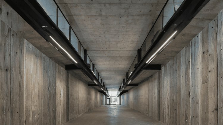
Long-corridor composite deck layouts present a distinct set of structural and logistical challenges that differ fundamentally from open-bay framing conditions. The narrow aspect ratio, typically widths of 8 ft to 20 ft running 60 ft to 200 ft or more, forces engineers to make deliberate decisions about framing orientation, span direction, deck gauge, and connection sequencing that would otherwise be routine in a conventional bay layout.
Narrow Geometry Amplifies Every Framing Decision
In a conventional bay, geometry provides flexibility. In a long corridor, width, partitions, MEP routing, deck span, beam behavior, and finishes become tightly interdependent.
A Highly Constrained Aspect Ratio
This elongated geometry sharply reduces the number of efficient framing solutions. Deck direction, supporting member locations, connection details, and service routing must respond to the same narrow structural zone.
Geometry Controls Nearly Every Design Variable
In a typical open floor bay, deck panels can run in multiple orientations and load paths are relatively forgiving. In a long corridor, the geometry constrains nearly every design variable: span length is dictated by corridor width, framing members must align with partition walls, and deck flute orientation directly affects both structural performance and MEP coordination clearance below.
Open-Bay Flexibility vs. Corridor Constraint
Greater Flexibility
Multiple deck orientations and framing arrangements may be viable, allowing designers to optimize around structural efficiency and service coordination.
Interdependent Decisions
Corridor width controls span while walls, openings, services, and finishes restrict framing placement and available structural depth.
Four Interdependent Design Pressures
Deck Span & Profile Selection
Span-to-width ratio often pushes designers toward 1.5-in. or 2-in. deck profiles to satisfy deflection limits without introducing intermediate supports.
Gravity Framing Coordination
Supporting framing must simultaneously accommodate corridor partition loads, door header conditions, and curtain wall connections, concentrating several framing responsibilities into the same narrow zone.
Camber & Finish Sensitivity
Camber requirements on supporting beams require tighter coordination because long corridor finishes can make elevation variation and floor profile changes particularly noticeable.
Concrete Topping Thickness
Topping thickness must balance fire-rating requirements, acoustic performance, structural dead load, and the limited floor-to-floor height available for both structure and building services.
Every Inch of Floor Depth Has Competing Demands
Decisions Must Be Made as a System
Long Corridors Reward Early Coordination
Framing orientation, deck profile and gauge, camber assumptions, partition loading, MEP clearance, and slab topping requirements should be reviewed together before the corridor layout becomes fixed. Resolving these relationships early prevents one discipline's optimization from creating problems for another.
Long Corridors Must Be Detailed as Integrated Structural Zones
Long-corridor deck layouts are governed by more than simple span requirements. Their narrow geometry links deck profile selection, framing alignment, partition loading, camber, MEP clearance, fire performance, acoustic requirements, and concrete topping depth into one tightly constrained system. Treating the corridor as a dedicated coordination zone from the beginning produces a more efficient structure and significantly reduces downstream detailing and construction conflicts.
Before the deck profile or panel layout is finalized, the framing orientation should be established. In long corridors, this decision affects beam quantity, deck span, deflection, MEP coordination, construction sequencing, and diaphragm continuity.
When panels span the short corridor dimension, the supporting beams run perpendicular to the corridor axis and the deck span remains relatively short. This is the most common arrangement because it can keep unsupported deck spans within a practical range and simplify construction-stage deck behavior.
Short unsupported spans generally make construction-stage deck behavior easier to control.
More intermediate framing increases steel tonnage and can create conflicts with existing MEP routes.
Many real corridor layouts combine both strategies. Cross-corridor beams can serve selected structural bays while continuous edge beams run along the corridor length. This approach becomes especially useful where the floor plate steps, changes width, or contains re-entrant corners.
At stepped or notched corridor transitions, coordinate deck endlaps, button-punch sidelaps, support geometry, and diaphragm continuity explicitly rather than relying on a typical bay detail.
Favor where short unsupported deck spans and construction-stage control are the primary drivers.
Consider where reduced intermediate framing is valuable and the deck, vibration, and construction-load criteria can support the longer span.
Use where corridor width changes, structural bays vary, or stepped geometry makes one orientation impractical across the entire floor.
Framing Orientation: The First Critical Decision
Deck Spanning Across the Corridor
Hybrid and Stepped Framing
Select the Configuration Using the Whole Corridor
The industry workhorse profile. Suitable for corridor spans up to approximately 10–11 ft in unshored composite construction with a standard 3.5-in. normal-weight concrete topping. Its shallow profile minimizes floor-to-floor height, making it ideal for tenant corridors with tight ceiling clearances. Shear stud placement is simple and efficient along standard beam widths.
Preferred for corridor spans between 10–14 ft or where reduced topping thickness is desired to minimize dead load. The wider flute accommodates conduit runs within slab depth, improving MEP coordination. Increased slab stiffness also reduces long-term creep deflection, benefiting sensitive flooring systems such as terrazzo and large-format tile.
Used for long-span corridor configurations exceeding 12–15 ft or when intermediate framing must be eliminated for architectural or MEP reasons. The deeper profile provides higher composite section capacity and lower live-load deflections, but increases slab thickness and dead load. Attachment detailing and shear connector installation require additional attention due to deeper flute geometry.
Deck profile selection is a balance between span capacity, floor depth, construction efficiency, and coordination requirements. The optimal solution depends on corridor geometry, loading demands, MEP integration, and long-term structural performance objectives.
Deck Profile Selection & Span Capacity
1.5-in. Composite Deck (Type B)
2-in. Composite Deck (Type Wide Rib)
3-in. Composite Deck (Deep Rib)
Critical Verification Requirements
Key Insight
Translating the structural framing concept into a buildable composite deck layout requires coordination across multiple disciplines and careful attention to the specific constraints of corridor geometry. The following workflow reflects best practice for long-corridor composite deck projects.
Composite deck panels typically come in standard lengths of 6 ft to 12 ft. In a long corridor, this means panel end-lap zones accumulate rapidly over the total run and must be intentionally positioned rather than allowed to occur wherever panel lengths happen to terminate.
Each end-lap requires minimum bearing on its supporting beam flange and should not land within a high-shear zone without explicit engineering consideration.
The deck layout drawing, separate from the structural framing plan, should identify every panel end, lap width, and closure plate at walls, columns, and slab edges.
Panel ends, lap widths, closure plates, walls, columns, and slab-edge conditions must be explicitly shown.
Side-lap fastener patterns, whether button-punch, screw, or weld, must be specified where elevated diaphragm demand exists.
A concrete placement sequence plan showing pump hose routing, screed rail locations, and the maximum allowable pour height at any single deck bay should be included in the structural documents or, at minimum, coordinated with the contractor before placement. Staged pours with defined construction joints help prevent overloading of partially loaded composite spans.
Long-corridor composite deck planning requires a disciplined progression from framing grid to deck profile, MEP coordination, panel layout, fastening, and erection documentation. Establishing a reliable corridor datum, explicitly locating every panel end and lap, coordinating closure conditions and beam camber, and planning concrete placement before field work begins prevents tolerance accumulation, bearing failures, diaphragm discontinuities, and construction-stage overloads. The result is a corridor layout that translates structural intent into predictable field execution.
Layout Planning: From Grid to Field Coordination
From Structural Grid to Erection Drawings
Lap Zones and Panel End Conditions
Every End Lap Needs Deliberate Support
Show the Geometry
Show the Fastening
Control the Moving Construction Load
What Must Be Resolved Before Erection
A Buildable Corridor Starts With a Controlled Layout
Deck span direction drives beam quantity, connection density, MEP coordination, and deflection behavior. Lock in the framing strategy before selecting deck profiles or advancing interdisciplinary coordination.
Published span tables provide guidance, but final selection must consider actual dead loads, concrete weight, construction loading, and corridor-specific geometric constraints.
Structural framing plans alone cannot capture all corridor deck requirements. Dedicated drawings should show panel layout, lap locations, edge closures, fastening patterns, bearing conditions, and pour-stop locations for accurate field execution.
Establish pour sequences, construction joints, and allowable load increments before placement begins. Long corridor pours can overstress unshored spans when pump loads, screeds, and wet concrete movement are not anticipated during design.
For advanced guidance on composite deck design, shear connectors, joist coordination, detailing practices, and engineering references, consult comprehensive steel deck documentation resources and project-specific manufacturer data.
Resolve Framing Orientation First
Match Deck Profile to Span and Load Reality
Produce a Dedicated Deck Layout Drawing
Plan the Concrete Placement Sequence
Further Technical Resources
Coordinate Often
Detail Precisely
What's Your Reaction?