Non-Composite Deck Bearing Details for Field Crews
When a steel deck is non-composite, it carries loads purely through its own profile — no concrete-to-steel interlock, no shear studs, no shared structural action. That distinction changes everything about how bearing must be detailed, verified, and installed in the field. Get it wrong, and you risk edge uplift, deck walking, and dangerous instability during concrete pour. This guide cuts straight to what ironworkers, deck installers, and foremen need to know on-site: minimum bearing lengths, seat conditions, fastener patterns, and the inspection checkpoints that keep a non-composite pour safe from start to finish.
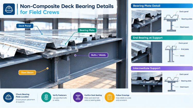
Why Bearing Details Matter on Non-Composite Decks
In composite deck systems, shear studs create a mechanical bond that helps stabilise the deck sheet at its ends. Non-composite decks carry no such benefit — the deck must transfer all load to the supporting beam or wall purely through its bearing seat and fasteners. This makes every millimetre of bearing length and every fastener location a structural decision, not just a site preference.
Edge Instability
During wet concrete placement, non-composite deck is subjected to its highest loading condition. Without adequate bearing and fastening, sheets can rotate at their ends, "walk" laterally, or partially lift off the beam flange — all while the pour is live. These are not minor deviations; they are failure events that can injure workers and compromise the slab.
Understanding the interaction between joist and deck bearing is critical before erection begins.
Bearing Length • Seat Flatness • Fastener Placement
The sequence below applies to standard non-composite steel deck placed on structural steel supports. Always cross-check against the project's erection drawings and the structural engineer's specifications — these steps establish best practice, not a substitute for project-specific requirements. For related steel joist detailing protocols, refer to the Consac joist detailing guide.
Confirm beam top flanges are level and within erection tolerances. Check that bearing surfaces are free of mill scale buildup, excessive camber, or weld spatter that could raise a sheet off the flange. Any beam that is high by more than 6 mm relative to adjacent framing must be reported to the site engineer before deck erection proceeds.
Snap a chalk line or mark each support beam to indicate the minimum bearing edge for the deck end. For steel supports, this is 38 mm (1½ in.) from the beam centreline to the nearest deck sheet edge — never less. On concrete or masonry bearing walls, increase this to 75 mm (3 in.) minimum.
These marks are your field QC baseline; a deck sheet that falls short of the line does not get welded.
Lay sheets in the direction specified on the erection plan. For non-composite deck, the sheet end must bear fully and continuously across the support — no gaps, no tilting, no bridging over an out-of-plane flange. Side-lap ribs must be nested correctly before any fastening begins. Misaligned side laps are a common source of bearing gaps that compromise load transfer.
Arc welds or powder-actuated fasteners at the deck ends (bearing supports) are the priority. These "button punches" or welds lock the sheet against lateral sliding and uplift. Weld washer requirements apply where the deck gauge is 22 ga. or lighter. Side-lap stitching follows bearing fasteners — never the reverse. Standard centres for end fasteners are typically 300 mm (12 in.) o.c. unless the structural drawing specifies closer spacing for wind uplift or pour pressure.
Side-lap stitching follows bearing fasteners — never the reverse.
Before the concrete truck arrives, the foreman or site engineer walks every bay: checking bearing length at edges, confirming fastener count matches the drawing schedule, verifying edge form attachment, and looking for any deck sheet that has shifted since installation. A simple tally sheet — one row per beam line — is the most reliable QC tool in the field.
Flag and fix before the pour; there is no correction after.
Field Installation: Step-by-Step Bearing Procedure
Verify Support Alignment Before Placing Deck
Establish and Mark Minimum Bearing Lines
Place and Align Deck Sheets
Fasten at Bearing Points First
Inspector Walk Before Concrete
Most non-composite bearing failures in the field are not caused by wrong materials or inadequate design—they are caused by installation shortcuts that look minor until the pour is underway.
The table below identifies the errors field crews encounter most often, their consequences, and the corrective action to take before concrete is placed. For deeper context on deck behaviour in structural systems, visit the Consac blog.
Verbal confirmation is not sufficient—use a written checklist tied to the pour sequence.
Common Field Errors &
How to Catch ThemNever begin a concrete pour until the foreman has signed off on a bearing and fastener inspection tally for every beam line in the bay.
Use this checklist as your final gate before concrete placement. Every item must be confirmed — not assumed. Print it, carry it on-site, and record the name of the person who verified each line. Non-composite deck has no shear stud safety net; the bearing detail is your only structural interface with the support below.
In non-composite systems, the deck-to-support interface is the only load path. Short bearing is a structural deficiency, not a site tolerance issue.
Always fasten end bearings before side laps. Reversing this sequence is the single most common installation error on non-composite decks.
Fastener centres, weld patterns, and bearing minimums can change from bay to bay within the same floor. Generic field practice does not substitute for drawing compliance.
A checklist walk takes 20 minutes. A bearing failure during a live pour can injure workers, waste an entire slab, and delay the project by weeks. The return on that 20 minutes is absolute.
For more technical resources on deck and joist coordination, visit the Consac joist and deck blog series and the full steel joist detailing guide.
Pre-Pour Checklist & Key Takeaways
Bearing Is Non-Negotiable
Sequence Matters
Read the Drawing, Every Bay
Stop Before You Pour
Bearing Is Non-Negotiable • Sequence Matters • Read the Drawing, Every Bay • Stop Before You Pour
What's Your Reaction?