Structural Load Distribution in Light Gauge Steel Floors
Understanding how loads transfer through light gauge steel floor systems is essential for designing safe, efficient, and cost-effective structures. This technical guide explores the mechanics, design considerations, and best practices for optimal load distribution.
Understanding Load Path Fundamentals
|
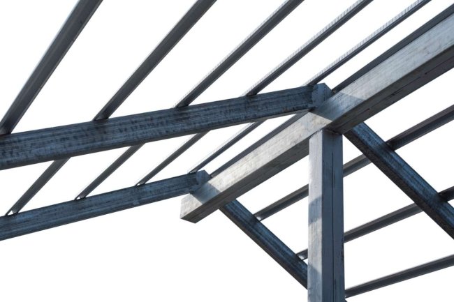
Load distribution in light gauge steel floors follows a systematic path from applied loads through joists, beams, and connections down to the foundation. The efficiency of this path directly impacts structural performance and material economy. Unlike traditional structural steel, light gauge members rely on thin-walled sections where local buckling, distortional behavior, and connection details become critical factors in load transfer mechanisms. |
|
Key Components of Load Distribution
Floor Joists
C-sections or track members spanning between supports, primarily resisting bending moments and shear forces from applied loads.
Bridging & Blocking
Lateral bracing elements that prevent joist rotation, distribute concentrated loads, and enhance overall system stiffness.
Deck Attachment
Sheathing connection creating composite action, transferring loads, and providing diaphragm strength for lateral stability.
Support Connections
Critical transfer points where vertical and horizontal forces move from joists to bearing walls or structural frames.
Load Types and Distribution Patterns
Light gauge steel floors must accommodate multiple load types simultaneously. Dead loads from the floor assembly itself create uniform distribution across all joists. Live loads from occupancy, furniture, and equipment vary in magnitude and location, requiring careful analysis of worst-case scenarios.
Point loads from columns, partitions, or concentrated equipment require special consideration. These loads must spread through the floor system efficiently, often necessitating joist doubling, additional blocking, or reinforced connections. Understanding how loads distribute both along individual members and across the entire floor diaphragm is crucial for optimization.
Design Considerations for Optimal Performance
Span-to-Depth Ratios
Maintain appropriate joist depths relative to span lengths to control deflection and ensure adequate stiffness without over-designing.
Joist Spacing Optimization
Balance material economy with structural requirements — typical spacing ranges from 12" to 24" on center depending on loads and deck type.
Connection Detailing
Specify fastener type, spacing, and edge distances precisely to achieve design load transfer without local failure or excessive deformation.
Deflection Control
Check both immediate and long-term deflection limits to prevent cracking in finishes, ensure proper drainage, and maintain serviceability.
Vibration Analysis
Evaluate floor natural frequencies and response to human-induced vibrations, critical in residential and office applications.
Moving Forward with Confidence
Key Takeaways
Effective load distribution in light gauge steel floors requires understanding the complete load path, addressing member-specific behavior such as web crippling and buckling, and detailing connections that transfer forces reliably.
By applying these principles—optimizing joist spacing, controlling deflection, providing adequate bracing, and coordinating through BIM—engineers can design efficient, economical floor systems that perform reliably throughout their service life.
Whether working on residential, commercial, or industrial projects, mastering these load distribution fundamentals will elevate structural designs and ensure successful project outcomes.
Common Load Distribution Challenges
Critical Issues
Engineers frequently encounter specific challenges in light gauge steel floor design that require specialized solutions and careful detailing.
Partnering with experienced firms like Consac, which provides comprehensive structural detailing and BIM services, can streamline the resolution of these complex distribution scenarios.
Web Crippling
Concentrated loads or reactions can cause local buckling at support points or load application areas, requiring bearing stiffeners or thicker sections.
Lateral-Torsional Buckling
Unbraced compression flanges may buckle laterally before reaching design capacity, necessitating adequate bridging and proper deck attachment.
Uneven Load Distribution
Non-uniform joist spacing or irregular support conditions create differential deflections and stress concentrations requiring careful analysis.
Connection Eccentricity
Offset connections introduce torsional moments and secondary stresses that must be accounted for in load transfer calculations.
Best Practices for Efficient Design
Standardize Member Sizes
Use consistent joist depths and gauges throughout each floor level to simplify fabrication, reduce errors, and improve construction efficiency.
Leverage BIM Coordination
Model complete floor systems including MEP penetrations early to identify conflicts and optimize member placement before fabrication begins.
Detail Connections Thoroughly
Provide clear, buildable connection details with specified fastener patterns, edge distances, and reinforcement requirements at critical locations.
Account for Tolerances
Design connections and support details with adequate tolerance for field conditions and normal construction variations in light gauge work.
What's Your Reaction?