How Form Deck Detailing Supports Slab Edge Accuracy
At the perimeter of any composite floor system, the slab edge is where structural intent meets field reality. Form deck detailing at this critical zone — where the deck terminates, where concrete is contained, and where gravity loads transfer to the supporting steel frame — demands precision that goes far beyond a simple flute closure. When details are resolved correctly at the drawing stage, contractors can set edge forms with confidence, concrete placement proceeds without costly remediation, and the finished slab meets both dimensional and structural tolerances.
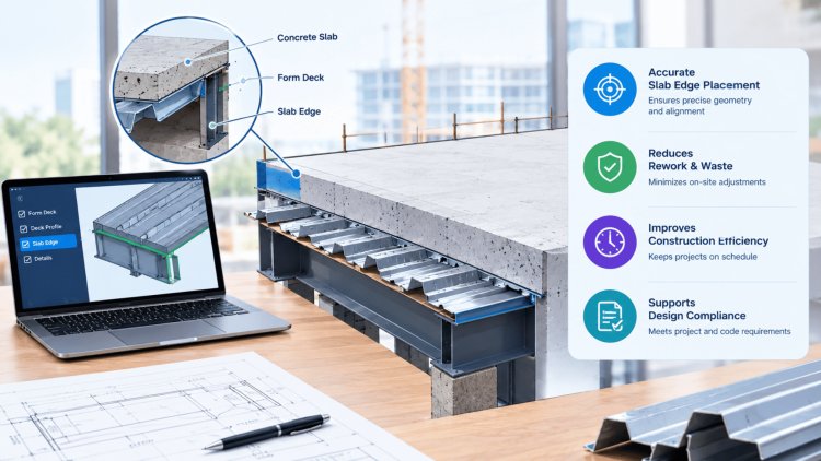
The Anatomy of a Slab Edge: What the Detail Must Resolve
A slab edge detail is not a single component — it is a system of coordinated elements, each performing a specific structural or formwork function. Understanding what each element contributes is the foundation of accurate detailing.
Pour Stop / Edge Form
The pour stop — typically a formed sheet metal angle or proprietary extrusion — retains concrete at the slab perimeter during placement. It must be sized to resist the hydrostatic pressure of wet concrete, account for deck camber, and align with the top-of-steel (TOS) elevation established by the structural engineer. Inadequate pour stop height or misalignment is among the most common sources of slab edge dimensional error in the field.
Flute Closure Strips
Where deck ribs run perpendicular to the supporting beam at the slab perimeter, open flutes must be closed to prevent concrete from flowing into the flute cavity. Closure strips — pressed steel or foam — are detailed to nest into the flute profile. Their correct specification, including the profile match (e.g., 1.5" Type B vs. 2" Type F), directly affects both concrete containment and the effective slab thickness at the edge.
Deck Bearing and Overhang
The deck sheet must bear a minimum distance onto the supporting steel — typically 1.5" minimum per SDI standards — while also being detailed so that the deck overhang beyond the beam face does not create an unsupported concrete cantilever that exceeds design assumptions. This bearing-to-overhang relationship governs both the structural adequacy of the edge and the feasibility of attaching the pour stop.
Edge Beam Interaction
The edge beam flange width, top flange elevation, and any fireproofing or spray-applied material thickness all influence how the deck, closure, and pour stop stack vertically. Detailers working with composite metal deck systems must account for these tolerances explicitly, not assume they will be resolved in the field.
A slab edge detail is not a single component — it is a system of coordinated elements, each performing a specific structural or formwork function.
Slab-edge form deck details must be coordinated against multiple governing documents simultaneously. The Steel Deck Institute (SDI) C-2017 Standard for Composite Steel Floor Deck–Slabs establishes minimum bearing lengths, end closures, and attachment requirements. ACI 318 governs concrete edge conditions and reinforcement cover at the slab perimeter. The project's structural drawings establish TOS elevations, beam sizes, and any special edge conditions such as spandrel beams, concrete spandrels, or masonry bearing.
Critically, the IBC and local amendments may impose additional requirements on edge conditions at fire-rated floor assemblies. Detailers should confirm whether the project's joist and deck detailing package includes fire-rated assembly requirements that affect the edge detail configuration, particularly regarding the height and continuity of the pour stop in relation to the UL-listed assembly.
Concrete blowout at the slab edge occurs when pour stops are undersized for hydrostatic pressure or are inadequately attached to the deck. This is a direct consequence of details that specify pour stop height without specifying attachment frequency or method.
Honeycombing and edge spalling result from open flutes at the slab perimeter that were not closed — either because the detail omitted closure strips entirely or specified the wrong profile. Concrete migrates into the flute, reducing edge coverage over reinforcement.
Elevation mismatches — where the finished slab surface steps at the edge — trace to pour stop heights set without accounting for deck camber under construction loads. The detail must specify pour stop height relative to the deflected deck position, not the theoretical flat-deck position.
Inadequate deck bearing at edge conditions is frequently discovered during erection when beam flange widths are narrower than assumed. Detailers referencing joist-and-deck coordination resources should always verify bearing against the actual steel section, not a nominal assumption.
Detailing Standards, Tolerances, and Common Field Failures
Governing References
Dimensional Tolerances to Enforce
Common Field Failures Traced to Detail Gaps
Effective BIM coordination for lightweight concrete slab systems goes far beyond clash detection. The integration of deck geometry, structural framing, embeds, edge conditions, and concrete slab parameters into a federated model requires disciplined data standards and intentional model management practices. The following workflow pillars represent current best practice for LWC deck coordination in multi-discipline BIM environments.
BIM Coordination Workflows
for LWC Deck Systems
A slab edge that is out of tolerance by even 3/8" creates cascading problems: cladding anchors miss their embedment targets, curtain wall sill conditions require shimming and field modification, and waterproofing transitions become difficult to detail correctly. In projects where the slab edge is also the structural diaphragm boundary, dimensional inaccuracy affects load path continuity — a concern that goes beyond aesthetics.
The investment in thorough, coordinated slab-edge form deck detailing pays dividends across every downstream trade. Concrete contractors set forms faster and with greater confidence. Steel erectors can verify bearing conditions before deck installation. Inspectors can check compliance against explicit dimensional criteria rather than interpretation. This is the practical value of technical precision at the drawing stage — it transfers decision-making from the field, where correction is expensive, to the office, where resolution is efficient.
Explore the full range of deck and joist detailing resources at Consac's structural detailing blog, including topics on composite deck behavior, joist bearing conditions, and coordination workflows for complex framing geometries. Whether you are a seasoned detailing specialist or expanding your expertise in steel joist and deck documentation, the slab edge is a consistently productive area for practice refinement.
TOS elevation, deck thickness, camber, construction tolerance, and pour stop height must all be coordinated in section before the plan detail is finalized.
Deck profile, closure strip type, pour stop gauge, and attachment method must be specified — not deferred to field judgment or "contractor's option."
Minimum 1.5" deck bearing must be verified against the actual beam flange width from the structural engineer's sections, not assumed from a nominal beam size.
Structural, architectural, and cladding details must agree at the slab edge. Flag and resolve conflicts at the detail stage to eliminate costly RFIs and field modifications.
Putting It All Together: Accuracy as a Deliverable
Why Edge Detailing Quality Compounds Across the Project
Key Takeaways for Detailing Specialists
Resolve the vertical stack before the plan
Name every component explicitly
Check bearing against actual sections
Cross-reference all affected drawing sets
The practical value of technical precision at the drawing stage — it transfers decision-making from the field, where correction is expensive, to the office, where resolution is efficient.
What's Your Reaction?