Joist Erection Drawings: Key Details for Safe Installation
In structural steel construction, joist erection drawings serve as the critical bridge between engineering design and field installation. These specialized documents provide fabricators, contractors, and erection crews with the precise information needed to safely install open-web steel joists—one of the most common and cost-effective framing systems in commercial and industrial buildings today.
What Are Joist Erection Drawings?
Joist erection drawings are detailed construction documents that translate the structural engineer's design intent into actionable installation instructions. Unlike general arrangement drawings, these specialized plans focus exclusively on the joist system—showing exact locations, sizes, connections, and sequencing for every joist member in the project.
These drawings typically include plan views, elevations, sections, and connection details that specify joist designations, bearing seats, bridging requirements, and anchorage details. They serve as the primary reference for steel erectors and become part of the permanent project record.
Essential Components of Joist Erection Drawings
Joist Identification
Each joist must be clearly labeled with its designation per Steel Joist Institute standards, indicating series, depth, and chord size. Unique member marks allow field crews to match shop-fabricated pieces to their intended locations without confusion.
Connection Details
Bearing seat types, weld specifications, and anchor bolt layouts are critical for load transfer. Drawings must show how joists connect to supporting beams, walls, or columns, including special conditions such as sloped or skewed connections.
Precise Placement
Dimensioned locations from building grid lines ensure accurate positioning. Joist spacing, cantilever lengths, and offsets from column centerlines must be clearly indicated to prevent field conflicts and maintain structural integrity.
Bridging Systems
Horizontal and diagonal bridging locations stabilize joists during and after erection. Proper bridging details prevent lateral buckling and ensure the joist system performs as designed under all load conditions.
The Role of Engineering Partners
Companies like Consac specialize in producing construction-ready joist erection drawings that meet both Steel Joist Institute standards and project-specific requirements. Their engineering teams coordinate closely with structural engineers, fabricators, and general contractors to ensure every detail supports safe, efficient installation.
By leveraging advanced CAD and BIM technologies, professional detailing firms can identify conflicts before fabrication begins—checking for interferences with mechanical systems, verifying load paths, and confirming that connection details are both constructible and code-compliant. This proactive approach prevents the field surprises that derail construction schedules.
Why Accuracy in Joist Drawings Matters
Incomplete or inaccurate joist drawings can impact safety, cost, and schedule. Precision ensures constructibility and reduces project risk.
Safety Implications
Incorrectly installed joists can fail under load, endangering workers and future occupants. Missing bridging or improper connections reduce system stability during construction.
Cost Overruns
Field changes due to drawing errors trigger costly rework—materials reordered, labor rescheduled, and work sequences disrupted. Minor errors on paper can cost thousands in the field.
Schedule Delays
Conflicts between drawings and site conditions halt work while engineers resolve discrepancies. Delays cascade through dependent trades, affecting roofing, MEP, and overall project completion.
Best Practices for Joist Installation Documentation
Clear, accurate, and coordinated joist documentation prevents errors, improves safety, and accelerates installation.
01. Coordinate Early with All Trades
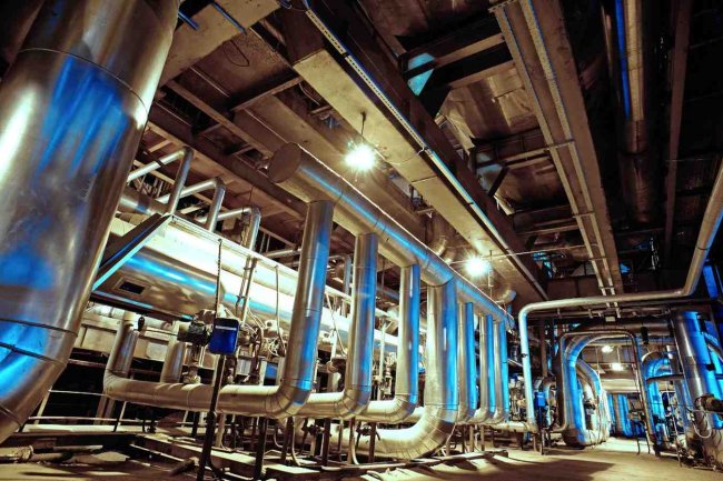
Share preliminary joist layouts with MEP engineers to identify conflicts before drawings are finalized. Early coordination prevents costly field modifications when ductwork, piping, or electrical conduits compete for the same space as structural members.
02. Include Comprehensive Notes
General notes should address erection sequences, temporary bracing requirements, welding procedures, and inspection hold points. Special conditions—like phased construction or existing structure tie-ins—require explicit callouts that field crews can't miss.
03. Provide Clear Connection Details
Standardize connection types where possible, but detail every exception. Show both plan and elevation views of complex connections, and include weld symbols that certified welders can execute without interpretation or guesswork.
04. Verify Against Structural Calculations
Cross-check every joist designation against the structural engineer's design documents. A single transposed number can specify an undersized member that appears identical but lacks adequate load capacity.
05. Maintain Revision Control
Track every change with clouded revisions and detailed revision descriptions. Field crews must know which drawing version represents current conditions—outdated drawings are as dangerous as no drawings at all.
Common Pitfalls to Avoid
Key mistakes that compromise field efficiency, safety, and constructability
Insufficient Dimensioning
Drawings that rely on scaling or assumptions force field crews to make decisions that should be engineering determinations. Every critical dimension must be explicitly stated, accounting for accumulated tolerances in long joist runs.
Neglecting Field Accessibility
Details that appear perfect on screen may be impossible to execute in the field. Consider crane reach, bolting access, and welding positions when developing connection details, and consult with erectors before finalizing designs.
Overlooking Temporary Conditions
Permanent bracing systems may not be installed until after joists are in place. Drawings must specify temporary bracing and installation sequences to maintain stability throughout the erection process.
Moving Forward with Confidence
Joist erection drawings represent far more than technical documentation—they embody the critical link between design intent and built reality. When executed with precision and attention to constructibility, these drawings enable safe, efficient installations that meet structural performance requirements while respecting budget and schedule constraints.
For project managers and contractors, investing in high-quality joist erection drawings delivers measurable returns through reduced field conflicts, faster installation, and improved safety outcomes. The most successful projects recognize that detailed engineering documentation isn't an expense to minimize—it's foundational infrastructure that supports every subsequent construction activity.
What's Your Reaction?