Joist and Deck Load Paths: Structural Design Considerations
Understanding how loads transfer through joists and decks is fundamental to safe, efficient structural design. Whether you're detailing a commercial building or coordinating a complex industrial project, mastering load path mechanics ensures structural integrity and code compliance.


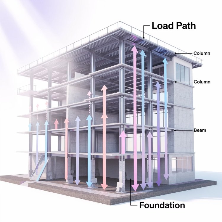
Understanding Load Paths in Structural Systems
Every structural system relies on a clear and continuous load path to safely transfer forces from occupied spaces to the foundation below.
Understanding how different loads affect joist systems is essential for safe structural design, accurate sizing, and long-term building performance.
Permanent structural weight including the deck, joists, beams, mechanical systems, ceiling assemblies, and finishes. Typically ranges from 20–50 psf depending on construction type and materials used.
Variable loads from occupancy, furniture, equipment, and human activity. Building codes specify minimum values such as 40 psf for offices, 50 psf for assembly spaces, and 125 psf for light manufacturing facilities.
Types of Loads Acting on Joist Systems
Dead Loads
Live Loads
Open-web steel joists and composite deck systems dominate commercial construction because of their efficiency, adaptability, and cost-effectiveness. Proper design requires careful consideration of loads, spans, serviceability, and connection detailing.
These prefabricated structural components span between beams and support floor or roof decking above. Proper joist selection depends on span length, load magnitude, deflection limits, and construction sequencing requirements.
Calculate total uniform load by combining dead, live, and environmental loads according to applicable building code requirements.
Choose K-Series for short spans, LH-Series for longer spans, or DLH-Series for deep long-span applications based on project requirements.
Ensure live-load deflection remains within accepted limits, typically L/360 for floors and L/240 for roof structures.
Joist Design Fundamentals
Determine Design Loads
Select Joist Type
Verify Deflection
Metal deck systems perform more than a gravity-support function. They also serve as structural diaphragms that transfer lateral forces safely throughout the building.
Metal deck does not simply carry floor or roof loads. It acts as a horizontal diaphragm that transfers wind and seismic forces to the building's lateral force-resisting system, creating a critical link in the overall structural load path.
Because of this dual role, diaphragm design requires careful attention to deck properties, attachment methods, and connection detailing to ensure both gravity and lateral loads are safely resisted.
Steel thickness directly affects diaphragm stiffness, strength, and load-transfer capacity.
Deck geometry influences spanning capability and diaphragm performance under lateral loads.
Side-lap connections and deck-to-joist fasteners determine how forces move across the diaphragm.
When structural detailing and BIM coordination are performed comprehensively, deck attachments, side-lap connections, and diaphragm load paths are precisely documented to satisfy both gravity and lateral force requirements. Proper detailing ensures the deck performs exactly as engineered throughout the building's lifespan.
Deck Diaphragm Behavior
More Than Gravity Support
Deck Gauge
Profile Depth
Fastener Pattern
Connections determine how forces move through a structure. Proper detailing ensures stability, safe load transfer, and reliable performance throughout construction and occupancy.
Critical Connection Design Points
Successful joist and deck design requires anticipating structural challenges early and implementing practical engineering solutions before they impact performance or construction schedules.
Common Design Challenges & Solutions
Successful joist and deck design depends on understanding load transfer, designing robust connections, and maintaining coordination across every discipline involved in the project lifecycle.
Every structural element and connection must transfer forces efficiently from the deck surface to the foundation. Weak links can compromise performance and safety.
Consider dead, live, wind, snow, and seismic loads during design. Building code minimums provide a baseline, but site-specific conditions often govern.
Connections are often the most critical and vulnerable points in a structural system. Proper detailing minimizes field modifications and construction risk.
Whether you're a project manager coordinating trades, an engineer designing connections, or a detailer preparing shop drawings, understanding joist and deck load paths is essential for delivering safe, economical, and constructible projects. Apply these principles consistently and you'll create structures that perform efficiently, minimize risk, and provide reliable service for decades.
Key Takeaways for Your Next Project
Understand the Complete Load Path
Account for All Load Types
Design Connections Carefully
Building Reliable Structures Starts with Smart Design
What's Your Reaction?